
Why Washington Boro Chemical Plants Can't Pick DAF or Clarifier on TSS Alone
A Washington Boro chemical plant operating in 2026 selects between a dissolved air flotation unit and a primary clarifier based on the full pollutant scan under 40 CFR Part 414 (Organic Chemicals, Plastics & Synthetic Fibers), not on TSS alone — Part 414 covers conventional pollutants (BOD, TSS, O&G, pH) and non-conventional pollutants (COD, TKN, phenols, sulfides, total chromium, hexavalent chromium, ammonia) that determine whether light, buoyant solids or dense inorganic precipitates drive the equipment decision. PA DEP Chapter 95 (PA Code Title 25, Chapter 95) governs effluent sampling, reporting and discharge limits for any direct discharger, while the Lancaster County Sewer Authority (LCSA) applies local limits and BOD/TSS surcharges to indirect dischargers — meaning a Washington Boro plant's permit envelope is shaped by three overlapping authorities.
TSS-only screening is misleading for chemicals because many organic-chemical reactions produce light, buoyant solids (latex, emulsion polymers, surfactant micelles, biological floc from on-site biotreatment) that a clarifier cannot settle but a DAF floats cleanly. The EPA Process Design Manual for Suspended Solids Removal (EPA 625/1-75-003a, 1975) defines the relevant fractions: soluble (<0.001 µm), colloidal (0.001–1 µm), supra-colloidal (1–100 µm) and settleable (>100 µm). A conventional clarifier targets the settleable fraction; a DAF with coagulation reaches the supra-colloidal and a portion of the colloidal fraction — which is the technical reason one unit alone rarely suffices for a chemicals stream carrying both light organics and heavy precipitates. This article scopes the comparison to the primary separation step only; downstream biology, metals precipitation, and membrane polish are separate design decisions, as covered in our chemicals wastewater DAF vs clarifier analysis for another U.S. chemical hub.
How a DAF System and a Clarifier Actually Work in a Chemical Plant
A dissolved air flotation system in a chemical plant pressurizes a saturated recycle stream (typically 30–80% of the throughput, or full effluent recycle on tight-mass-balance streams) with air at 4–6 bar in a saturator vessel, then releases the stream through a needle-valve manifold at the bottom of the flotation tank. Micro-bubbles in the 10–100 µm range nucleate on oil droplets, FOG, latex particles and conditioned floc, lifting them to the surface where a chain-and-flight or scoop skimmer removes the float layer. Hydraulic residence time is 15–40 minutes, depending on the recycle ratio and the bubble–particle attachment kinetics; bubble–particle attachment is the limiting step, and high surface-tension or high-ionic-strength streams benefit from a coagulant (alum, ferric chloride, or a cationic polymer) plus pH adjustment per EPA Process Design Manual Chapter 4.
A clarifier relies on gravity sedimentation. EPA 625/1-75-003a (1975) Chapter 7 defines three operating regimes: plain settling for discrete particles, flocculent settling for low-concentration colloids after coagulation, and zone/compression settling for activated-sludge blankets in secondary clarifiers. Internals are rectangular or circular, frequently fitted with tube settlers or lamella plates inclined at 55–60° — the EPA 1975 manual documents tube-settler retrofits that boost clarifier capacity 2–4× without new tankage (Chapter 7, Figures 7-8 through 7-11). Mechanically, a clarifier depends on particle specific gravity >1.0, so light organics, oils and latex will not settle without chemical conditioning or dissolved-air assist — which is why the two technologies are complements, not substitutes, in most chemicals plants.
Footprint is a direct differentiator: a DAF at comparable hydraulic loading occupies roughly 50–70% of the footprint of a conventional clarifier, which matters on tight chemical-plant pads in the Washington Boro industrial corridor. A HydropureWater ZSQ dissolved air flotation system sized to the same flow as a gravity clarifier frees pad space for equalization or chemical dosing skids, and a HydropureWater lamella clarifier as a downstream polishing step preserves the footprint advantage for the full train.
Side-by-Side: Removal Efficiency, Footprint, OPEX and Chemical Tolerance
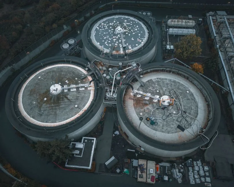
The comparison below mixes EPA Process Design Manual figures for primary clarifier overflow rates and DAF loadings with the Ecologix 2026 removal-efficiency data and field-validated OPEX benchmarks from World Water Works case studies. Use it to sanity-check vendor quotes and to brief procurement and compliance in the same meeting.
| Parameter | DAF (Dissolved Air Flotation) | Primary Clarifier (incl. lamella/tube settler) |
|---|---|---|
| Target contaminant | Oil, FOG, latex, surfactant, light polymer, biological floc | Dense inorganic precipitates, metal hydroxides, settleable TSS >100 µm |
| Removal efficiency (chemicals stream) | ~95% O&G; 85–95% TSS with coagulation (Ecologix 2026) | ~70% O&G; 90–95% TSS on heavy/inorganic streams (Ecologix mining case, 2026) |
| Hydraulic residence time | 15–40 minutes | 2–4 hours primary; 60–90 min with tube settlers |
| Footprint at equal flow | 50–70% of a conventional clarifier | Reference baseline; lamella internals recover 2–4× capacity (EPA 1975, Ch. 7) |
| Chemical conditioning demand | Higher (coagulant + polymer for floc strength) | Lower; mainly coagulant for fine TSS capture |
| OPEX driver | Saturator/recycle pump power + polymer + skim disposal | Sludge pumping + polymer (lower dose) + rake torque |
| Flow-spike sensitivity | High — skimmer efficiency drops fast on hydraulic overload (Butterball retrofit, World Water Works) | Moderate — tolerates short-term flow spikes better |
| Construction (chemicals service) | Specify SS304/316 or FRP wetted parts for pH <3 or >11, chlorides >500 mg/L, trace HF | Same material logic; mild steel acceptable for neutral brine |
| Typical 2026 indirect-discharger payback lever | Documented $20,000+/month surcharge reduction on a $30,000+/month bill (World Water Works dairy case) | Slower payback; suited to plants with low BOD/FOG but high settleable TSS |
For a Washington Boro plant handling HCl, NaOCl, ferric chloride or HF, the RFQ must specify wetted-material construction, not just flow rating — a mild-steel DAF tank in a chlorinated stream is a 12–18 month failure mode. A HydropureWater automatic chemical dosing skid paired with either unit stabilizes the coagulation chemistry and reduces the operator-attention penalty that drives up OPEX on undersized installations. Cite the EPA Process Design Manual chapters 4 (chemical coagulation), 5 (storage and feeding) and 7 (gravity separation and flotation) as the design basis on every submittal.
When a DAF Is the Right Primary for a Washington Boro Chemical Plant
Specify a DAF as primary when the stream signature shows free oil above ~50 mg/L, emulsified oil, FOG, latex or polymer solids, surfactant-laden washwater, biological sludge from an on-site biotreatment step, or a product changeover stream with light organics. Plant-level triggers include a tight pad (under ~30 m² available for primary treatment), a sewer surcharge dominated by BOD/FOG, or an oil-and-grease permit limit under 40 CFR Part 414 subparts G and H that a clarifier cannot meet reliably — Part 414 subparts establish O&G and TKN limits that a DAF can hit without activated sludge, which is relevant for plants that want to avoid biological treatment. The $20,000+/month surcharge reduction documented by World Water Works on a dairy operation that was billed over $30,000/month is a conservative proxy for a Washington Boro indirect discharger to LCSA, where the surcharge arithmetic is comparable.
Operationally, a DAF supports rapid startup and shutdown, batch chemistry, and seasonal variation — a modern skid-mounted ZSQ-series unit is fully automatic and can be turned down or idled between campaigns without the sludge-blanket issues that plague idled clarifiers. Skid delivery from 4 m³/h upward, paired with an automatic chemical dosing skid, supports a 2026 capex cycle: install and commission in weeks, not months, which is the right tempo for a batch specialty-chemical plant running multiple product changeovers per week. Specialty paper mills and meat processors that benchmarked legacy clarifiers against DAF retrofits — both referenced in the World Water Works case library — illustrate the upgrade-from-clarifier-to-DAF decision specialty-chemicals plants face when product mix shifts toward emulsions and polymer dispersions.
When a Clarifier Wins — and When You Should Run a Hybrid Train
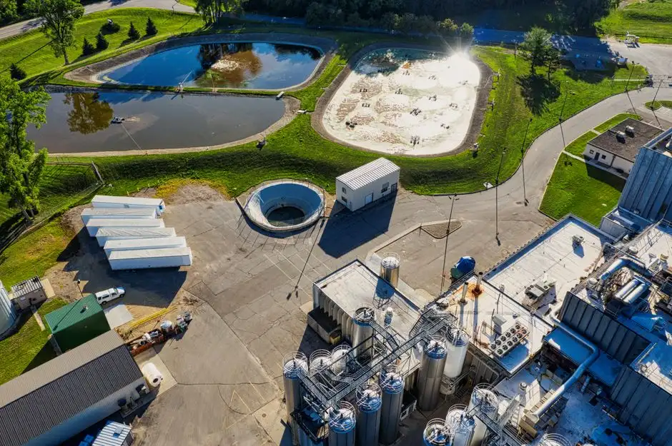
A conventional or lamella clarifier wins on heavy inorganic precipitates (CaCO3, CaSO4, metal hydroxides from pH adjustment for metals removal), high-TSS streams above 2,000 mg/L, low-FOG process water, and brine streams where the polymer dose is the OPEX line that decides the project. The EPA Process Design Manual (1975) Chapter 7 documents primary clarifier overflow rates of 600–1,200 gpd/ft² at 50–70% TSS removal, with tube-settler retrofits reaching 2–4× the effective surface loading. The hydrometallurgy step at most Washington Boro inorganic-chemical plants (ferric or ferrous sulfate coagulation, lime softening, hydroxide precipitation of nickel or chrome) produces a settleable solids stream that is the wrong target for a DAF and the right target for a clarifier — a DAF would waste saturator power on particles that already settle under gravity.
The hybrid train — DAF as primary to remove FOG, oil and buoyant latex, then a lamella clarifier (tube settler) as secondary to capture fine settleable solids and the chemical precipitate — is the design pattern in most pharmaceutical and specialty-chemical plants and matches EPA 1975 manual tube-settler retrofits. A lamella clarifier reaches 20–40 m³/h per m² of surface loading with up to 30% lower chemical consumption than a conventional clarifier, making it the right secondary polishing step after a DAF. Even within a single plant, DAF-vs-clarifier is an ongoing retrofit decision: Great Lakes Pulp & Fibre, for example, evaluated DAF to cut OPEX on two existing DAF units — the technology selection is revisited every time a permit limit tightens or a production line changes. Plan the downstream sludge-handling step in parallel: both DAF and clarifier float or settle sludge that needs a plate-and-frame filter press for dewatering, and that equipment is the next bottleneck in the train.
A 2026 Selection Framework for Washington Boro Chemical Plants
Run this six-step sequence on a Monday morning and the equipment decision will follow from the data, not from vendor preference.
- Pollutant scan against 40 CFR Part 414 subparts and PA DEP Chapter 95. List every parameter — BOD, TSS, O&G, COD, TKN, phenols, sulfides, total chromium, hexavalent chromium, ammonia — with influent concentration and permit limit. Anchor the list in the categorical standard and the state chapter, not in a vendor's standard scope of supply.
- Classify each parameter as "floats" or "settles." Oil, FOG, latex and light polymer → DAF. Metal hydroxide, CaCO3 and high TSS → clarifier. Parameters that fall in both categories point directly to a hybrid train.
- Default to a hybrid DAF-primary + lamella-clarifier-secondary train when both categories exist in significant quantity. Most Washington Boro batch and specialty-chemical plants land here, and the hybrid matches the EPA Process Design Manual Chapter 7 tube-settler retrofit logic.
- For indirect discharge to LCSA, model the BOD/TSS surcharge savings a DAF would deliver. Use the World Water Works $20,000+/month surcharge reduction case as a sanity check on the order of magnitude. A DAF pre-treat rarely pays back on direct-discharge chemistry alone, but it almost always pays back on indirect-discharge surcharges.
- Size with 20–30% hydraulic margin above peak flow and confirm wetted-material construction (SS316 or FRP) for any stream with pH below 3 or above 11, chlorides above 500 mg/L, or trace HF. A DAF that passes a hydraulic check but fails a materials check is a 12–18 month failure mode.
- Pair the primary unit with an automatic chemical dosing skid and a downstream sludge dewatering unit so the primary treatment is not a stand-alone bottleneck. Coverage of the dosing and dewatering selection is in our Plano chemicals wastewater DAF/clarifier comparison and in the broader 2026 BOD and effluent compliance guide.
Frequently Asked Questions
For a chemical plant in Washington Boro, PA, should we choose a DAF or a clarifier in 2026?
The choice is contaminant-driven. Specify a DAF for oil, FOG, latex and light polymer streams (the 95% O&G removal band); specify a clarifier for heavy inorganic precipitates and high-TSS streams; default to a hybrid DAF-primary + lamella-clarifier-secondary train for most batch and specialty-chemical plants that produce both fractions. Match the selection to the 40 CFR Part 414 subpart and PA DEP Chapter 95 limits that govern the permit, not to a vendor's standard scope.
What is the typical DAF removal efficiency for oil and grease in a chemical plant?
A DAF with proper coagulation typically delivers ~95% O&G removal on chemicals streams, versus ~70% for a clarifier on the same feed (Ecologix 2026 field data). The gap widens when the stream carries emulsified oil or surfactant-stabilized droplets that gravity cannot break.
How much can a DAF pre-treat cut municipal sewer surcharges?
Documented cases show $20,000+/month reductions on surcharges that were over $30,000/month before the DAF pre-treat was installed (World Water Works dairy case). For an indirect discharger to LCSA, run a BOD/TSS surcharge model on the current bill before sizing the unit — the payback period is often under 24 months at 2026 surcharge rates.
Does a clarifier meet 40 CFR Part 414 O&G limits on its own?
Rarely. A clarifier typically delivers ~70% O&G removal versus the categorical limits in 40 CFR Part 414 subparts G and H, so most chemicals plants add a DAF primary or a biological polishing step to reach the O&G envelope. A DAF hits the limit without biology, which avoids the activated-sludge capex and operator-attention burden.
What construction material is required for a DAF handling acidic or chlorinated chemical streams?
Specify stainless 304/316 or FRP wetted construction; do not accept mild steel for streams with pH below 3 or above 11, chlorides above 500 mg/L, or trace HF. The wetted-material specification belongs on the RFQ as a separate line item from the flow rating.
How is a lamella clarifier different from a conventional clarifier for a chemical plant?
A lamella clarifier uses inclined-plate or tube internals to raise the effective surface loading to 20–40 m³/h per m² and cut polymer use by up to 30% versus a conventional clarifier of equal footprint. It is the right secondary polishing step after a DAF and matches the tube-settler retrofit pattern documented in EPA 625/1-75-003a (1975) Chapter 7.