Why Sweeny-Area Bulk Plants Are Under Tighter Pretreatment Pressure in 2026
Petroleum bulk plants in the Brazosport/Sweeny corridor are absorbing three converging pressures in 2026, and the math is unforgiving. First, the receiving POTW infrastructure on the Texas Gulf Coast is operating past its original design horizon for both hydraulic and biosolids capacity, so headworks loadings that were tolerated a decade ago now push activated-sludge systems past their nitrification envelope. Second, EPA's 2024–2026 National Pretreatment Program (NPP) review cycle has prioritized audit frequency at refining-adjacent SIUs in Texas water-stressed basins, which means Brazosport-area terminals can expect an unannounced walk-through rather than a scheduled inspection. Third, intensifying water-reuse demand across the Brazos River basin is forcing stricter discharge ceilings: the ACS ES&T Engineering 2021 review on U.S. industrial water scarcity documents that reuse-driven POTWs are systematically tightening daily-maximum O&G limits by 30–60% over a five-year horizon.
A Notice of Violation (NOV) citing a single HEM exceedance carries a 30-day cure window. If the next two monthly reports miss, the event escalates to Significant Noncompliance (SNC) — and an SNC can trigger administrative orders, surcharges, mandated zero-discharge status, or permit termination. For a Sweeny-area bulk plant sitting on the Brazosport Water Authority's receiving system, that means the local limit printed on a 2024 permit is not the number the engineer should design to in 2026; the trajectory of that number matters more than the current value.
The Regulatory Chain That Sets Your Permit Numbers
Every number on a petroleum bulk plant's discharge permit traces back to a specific citation in a five-link chain, and the engineer defending an audit finding should be able to walk the chain forward and backward. The chain runs: Clean Water Act of 1972 (33 U.S.C. § 1251 et seq.) → EPA General Pretreatment Regulations at 40 CFR Part 403 → POTW-adopted Technically Based Local Limits (TBLL) derived using the EPA Maximum Allowable Headworks Loading (MAHL) method → Maximum Allowable Industrial Loading (MAIL) allocation for each Industrial User → the daily-maximum and monthly-average numbers printed on the discharge permit. The MAHL methodology is documented in EPA's 2004 (updated) Local Limits Development Guidance and applied in practice as demonstrated in the 2020 St. Joseph, MO TBLL evaluation by Black & Veatch, final report adopted 2020-12.
Four inputs feed every MAHL calculation: NPDES permit limits on the receiving POTW, state water quality standards for the receiving stream, biosolids disposal criteria (typically Part 503 numerical limits on metals and organics), and local worker/ecosystem protection factors such as NIOSH thresholds and aquatic toxicity data (per St. Joseph 2020 TBLL). The POTW converts the MAHL into a MAIL for each Industrial User, then allocates mass against flow, producing the daily-maximum and monthly-average limits on the permit.
The Industrial User trigger is broad: any discharger that meets the IU criteria — facilities that discharge process wastewater to a POTW, or that contribute ≥25,000 gpd of non-domestic waste — is an IU under 40 CFR Part 403. Most petroleum bulk plants fall under noncategorical Significant Industrial User (SIU) status; dedicated refinery or fuel-blending operations may be categorical. Once the permit is issued, the operator owns the daily free-oil inspection log, the monthly HEM composite result, and the 30–60 day cure window. The eight specific prohibitions at 40 CFR § 403.5(b) cover flashpoint <140 °F (60 °C), pH <5.0, solids causing obstruction, heat >40 °C (104 °F) at the POTW, petroleum/mineral oil causing pass through or interference, toxic gases, and hauled waste at undesignated points (per EPA, Pretreatment Standards and Requirements).
What Your Permit Actually Says: HEM, TSS, BTEX, and TPH
Hexane Extractable Material (HEM) is the federally used proxy for fats, oils, and grease in U.S. pretreatment, defined at 40 CFR § 401.16 and measured by EPA Method 1664A using n-hexane extraction. This is the parameter most bulk-plant permits cite as "O&G" (per St. Joseph 2020 TBLL). Typical 2026 permit ceilings fall at 100–200 mg/L HEM daily maximum and ~250 mg/L TSS, but stricter POTWs in water-reuse basins — including segments of the Brazosport receiving system — are pushing daily-maximum HEM toward 50 mg/L.
The watchlist parameters are BTEX (benzene, toluene, ethylbenzene, xylene) and total petroleum hydrocarbons (TPH), each sized to the local MAHL allocation. Engineers should treat benzene and TPH as the lead parameters for permit negotiation, because the MAHL they generate often constrains allowable daily flow more than O&G does. A facility that defends only its HEM number while ignoring its benzene load can find itself in compliance on oil and grease but in violation on flow allocation.
The Four-Stage Pretreatment Train and Why the Order Is Non-Negotiable
A defensible petroleum bulk plant pretreatment train has four stages, and the sequence is not optional.
Stage 1 — Source segregation. Keeping hydrocarbon-contaminated streams out of clean stormwater avoids triggering EPA Multi-Sector General Permit (MSGP) thresholds and shrinks the volume hitting the train. Field retrofits show 40–70% volume reduction through segregated laterals on product-handling pads, covered dump valves, and dedicated oil/water sewering on truck loading islands (HydropureWater field data, 2025–2026). Source segregation converts most of the remaining flow from a design problem into a design choice.
Stage 2 — Primary oil/water separation. An API gravity separator, a CPI corrugated plate interceptor, or a plate/media coalescer handles the free-oil fraction (droplets ≥60–150 µm). For API units, a residence time of at least 30 minutes at peak flow is the standard reference; CPI plate spacing typically falls in the 1–2 inch range, with corrugation angle near 45°.
Stage 3 — Emulsified-oil polishing. A Dissolved Air Flotation (DAF) system floats oil droplets down to roughly 10–25 µm using micro-bubbles generated at 60–90 psig. DAF is the only physical stage that addresses the sub-60 µm fraction produced by detergent-bearing wash-rack water.
Stage 4 — Biological or adsorption polishing. Applied only where the local limit demands ammonia, sulfide, or dissolved hydrocarbon reductions a physical train cannot deliver. The options are MBBR, activated sludge, or granular activated carbon (GAC).
The principal waste streams each stage must serve are tank-bottom water, API/coalescer dumps, truck and rail loading drip, vehicle wash-rack wastewater, hydrostatic test water, and stormwater that contacts product-handling areas. Each stream carries a different droplet-size distribution: tank-bottom water is typically free oil plus sludge; wash-rack water is emulsified (surfactants drive droplet sizes below 50 µm); loading-arm drip is mostly free oil. That is why a single-technology approach fails — a CPI alone cannot break emulsions, and a DAF alone is overwhelmed by a slug of free oil during a coalescer dump.
Choosing the Right Primary Separator and Polisher
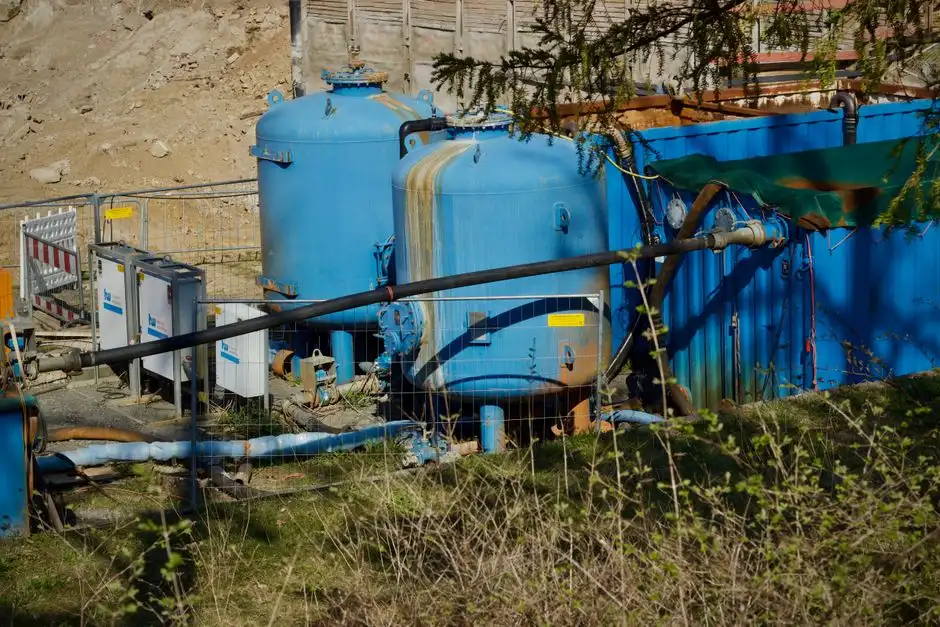
The four primary-technology options sit in different performance bands and are not interchangeable. The selection matrix below maps the realistic droplet-size band, hydraulic loading, footprint, and O&G residual for each.
| Technology | Droplet Size Band | Hydraulic Loading | Footprint | Typical O&G Residual | Best Fit |
|---|---|---|---|---|---|
| API Gravity Separator | ≥150 µm (free oil) | ~0.5–1 gpm/ft² | Large | 50–100 mg/L downstream of skimming | High-throughput marine terminal, large flow swings |
| CPI (Corrugated Plate Interceptor) | 60–150 µm | 3–5 gpm/ft² | Compact vs. API | 50–100 mg/L on free-oil streams | Small-to-mid terminal with steady flow; retrofit into existing concrete vault |
| Plate/Media Coalescer | 10–25 µm (emulsified/colloidal) | 2–5 gpm/ft² surface; ASR ~0.02–0.05 | Compact; vertical configs available | 30–75 mg/L | Truck-loading rack with emulsified oils; primary where free oil is pre-strained |
| DAF (Dissolved Air Flotation) | 10–25 µm (emulsified) | 2–5 gpm/ft² surface hydraulic loading | Compact; vertical configs available | <50 mg/L achievable with chemistry | Polishing stage or low-flow sites with strict <50 mg/L needs |
Field guidance is clear: a DAF alone without a primary gravity stage fails under slug loads from coalescer dumps, because free oil blankets the bubble surface and crashes the air-to-solids ratio (HydropureWater field data, 2026). A CPI alone rarely meets a 100 mg/L HEM limit on emulsified wash-rack water — it removes free oil efficiently but does not address sub-60 µm droplets. The robust path for a U.S. petroleum bulk plant is CPI or API as primary, then DAF as the emulsified-oil polisher, sized with a 20–30% safety margin on hydraulic and air-to-solids loading. For pH adjustment and demulsifier feed, an integrated HydropureWater automatic chemical dosing system keeps the chemistry within the 6.5–7.5 window the DAF requires.
Worked Example: Sizing the DAF Stage for Tank-Bottom Water
Three numbers drive a defensible DAF design: peak instantaneous flow (gpm or m³/h, not the daily average — slug loads during a coalescer dump or a tank drop can spike 3–5× the daily mean), daily O&G load (lb/day or kg/day, calculated from tank turnover, wash-rack volume, and drip rates), and target residual O&G (mg/L, taken from the local permit ceiling or, ideally, set 20–30% below it). Designing on the daily mean is the single most common sizing error in field retrofits.
The DAF design parameters are: surface hydraulic loading 2–5 gpm/ft² in oilfield service; air-to-solids ratio with a 20–30% safety margin to absorb slug loads; micro-bubble generation at 60–90 psig; and pH adjustment to 6.5–7.5 ahead of the flotation cell. Chemistry closes the residual gap: a demulsifier or coagulant dose of 50–200 mg/L fed through a HydropureWater automatic chemical dosing system is what unlocks the <50 mg/L HEM residual a strict POTW will demand. The Dissolved Air Flotation (DAF) system covers 4–300 m³/h across 13 standard models, with automatic skimming that handles the floated oil layer without operator intervention.
Worked sizing illustration: a Sweeny-area terminal with a 50 mg/L HEM permit handling tank-bottom water at a peak instantaneous flow of 120 gpm (27 m³/h) and an estimated daily O&G load of 220 lb/day. The design residual target is set at 35 mg/L (30% below the permit ceiling). Required surface area = peak flow / hydraulic loading = 120 gpm ÷ 3 gpm/ft² = 40 ft² (≈3.7 m²) — well within the DAF standard-model range. Air-to-solids ratio is set with a 25% safety margin above the calculated minimum to absorb coalescer-dump slugs. Where the train has to swing from a 50 mg/L HEM permit to <20 mg/L for a water-reuse loop, the polishing step moves from biological (MBBR or activated sludge) to adsorption (GAC). The summary table below maps the worked numbers to the DAF operating envelope:
| Design Parameter | Value / Range | Source / Basis |
|---|---|---|
| Peak instantaneous flow | 120 gpm (27 m³/h) — design on peak, not mean | Slug-load envelope per HydropureWater field data, 2026 |
| Daily O&G load | 220 lb/day (100 kg/day) | Tank turnover + wash-rack + drip inventory |
| Permit ceiling | 50 mg/L HEM daily max | Water-reuse basin local limit |
| Design residual | 35 mg/L (30% margin below ceiling) | Engineering practice for safety margin |
| Surface hydraulic loading | 2–5 gpm/ft²; 3 gpm/ft² selected | Oilfield DAF standard |
| Required surface area | ~40 ft² (3.7 m²) | Peak flow ÷ hydraulic loading |
| Air-to-solids ratio (ASR) | 20–30% safety margin over calculated minimum | Slug-load absorption |
| Micro-bubble generation | 60–90 psig saturation | DAF design standard |
| pH window | 6.5–7.5 ahead of DAF | Flotation chemistry optimum |
| Demulsifier / coagulant dose | 50–200 mg/L | Residual <50 mg/L HEM target |
| DAF model range | 4–300 m³/h, 13 standard models | DAF specification |
| Polishing (reuse loop) | MBBR or GAC to <20 mg/L | Water-reuse swing requirement |
Self-Monitoring Cadence and BMPs That Prevent an SNC Finding

The minimum 2026 self-monitoring cadence most POTWs expect from a petroleum bulk plant: daily visual free-oil inspection at the outlet weir (logged on a dated and initialed paper or digital sheet), weekly TSS grab, monthly HEM composite (EPA Method 1664A, 24-hour flow-proportional where the permit specifies), and a 24-hour flow-proportional composite for BTEX/TPH where the local limit is non-zero. Sampling taps must be accessible, the flow meter calibrated annually, and the chain-of-custody defensible — most SNC findings originate from sampling-procedure deficiencies, not from underlying treatment performance.
Best Management Practices (BMPs) are the cheapest compliance insurance a terminal can buy. The BMPs the POTW pretreatment coordinator looks for include spill containment around all aboveground storage tanks, drip pans under truck loading arms, covered and locked dump valves on coalescers, segregated sewer laterals keeping product-handling pads out of the clean stormwater system, and visible tagging of all sample points. A written Spill Prevention and Countermeasure Plan (SPCC, 40 CFR Part 112) tied to the sewer map eliminates roughly half of common audit findings (HydropureWater field data, 2025). The table below maps each BMP and self-monitoring line to the EPA National Pretreatment Program audit checklist category it satisfies:
| Self-Monitoring / BMP Item | Frequency / Standard | EPA NPP Audit Checklist Category |
|---|---|---|
| Visual free-oil inspection at outlet weir | Daily, dated and initialed | Monitoring & Reporting |
| TSS grab sample | Weekly | Monitoring & Reporting |
| HEM composite (EPA Method 1664A) | Monthly, 24-hr flow-proportional | Monitoring & Reporting / Analytical Methods |
| BTEX/TPH composite (where limit non-zero) | Monthly, 24-hr flow-proportional | Monitoring & Reporting |
| Flow meter calibration | Annual | Instrumentation / Recordkeeping |
| Chain-of-custody documentation | Each sampling event | Recordkeeping / Sampling Procedures |
| SPCC plan tied to sewer map | 40 CFR Part 112, current revision | Slug Control / SPCC |
| Spill containment around ASTs | Continuous, integrity inspected | Slug Control / BMP |
| Drip pans under loading arms | Continuous, emptied per SOP | BMP / Source Segregation |
| Covered, locked coalescer dump valves | Continuous access control | Slug Control / BMP |
| Segregated sewer laterals on product pads | Per sewer map, locked tags | Source Segregation / Sewer Map |
| Visible sample-point tagging | All compliance sampling locations | Sampling Procedures / BMP |
The Consequence Matrix and a 30–60–90 Day Action Plan
The escalation chain is linear and avoidable. One late monthly report triggers a Notice of Violation; two in twelve months escalate to SNC; SNC triggers a Show Cause hearing and potential permit action including administrative orders, surcharges, mandated zero-discharge status, or permit termination. The audit cost of an SNC finding typically exceeds six figures once legal, engineering, and capital-rebuild costs are summed, and a single SNC can halt product-handling operations if the POTW imposes a zero-discharge order. A terminal that runs the BMP list above, files reports on the 15th of every month without exception, and keeps a pre-audit file mapped 1:1 to the EPA National Pretreatment Program audit checklist categories will not see an SNC finding in 2026.
For a terminal that already has a problem, the 30–60–90 day playbook is: Days 1–30 — audit the sewer map against the SPCC plan, install source segregation where it is missing, and verify sampling taps and chain-of-custody. Days 31–60 — pull the last 12 months of HEM/TSS/BTEX/TPH data and benchmark against the MAHL-derived permit numbers. Days 61–90 — close gaps with primary separation upgrades, DAF polishing capacity, and chemistry controls, then lock in the monthly reporting cadence on the 15th. Where a terminal needs a fast-track bridge, documented in the emergency DAF case study for a failing FOG lagoon, rental DAF capacity plus temporary chemistry rebalancing buys 60–90 days of compliance runway while a permanent rebuild is engineered. For facilities that prefer an outsourced operating model, the engineering scope of performance-based wastewater O&M contracts is worth reviewing as a hedge against repeat findings. The table below sequences the actions against the audit categories they close out:
| Window | Action | EPA NPP Audit Category Closed Out |
|---|---|---|
| Days 1–30 | Audit sewer map vs. SPCC; install source segregation; verify sampling taps and COC | Sewer Map, SPCC, Sampling Procedures, BMP |
| Days 31–60 | Pull 12-month HEM/TSS/BTEX/TPH; benchmark against MAHL-derived limits | Monitoring & Reporting, Analytical Methods, MAHL Allocation |
| Days 61–90 | Install primary separation upgrade, DAF polish, chemistry controls; lock 15th-of-month reporting cadence | Slug Control, BMP, Recordkeeping, Reporting Cadence |
Frequently Asked Questions
What are typical 2026 HEM and TSS permit ceilings for petroleum bulk plants near Sweeny?
Most 2026 permits set HEM (oil and grease) at 100–200 mg/L daily maximum and approximately 250 mg/L TSS, derived using EPA's MAHL method under 40 CFR Part 403 (per the 2020 St. Joseph, MO TBLL evaluation by Black & Veatch). Stricter POTWs in water-reuse basins push daily-maximum HEM toward 50 mg/L.
Can a DAF system treat tank-bottom water without a primary oil/water separator ahead of it?
In most cases, no. Free oil from coalescer dumps and tank drops blankets DAF micro-bubbles and crashes the air-to-solids ratio; a DAF alone fails under slug loads (HydropureWater field data, 2026). A CPI or API primary stage ahead of the DAF is standard practice for slug-load protection.
What triggers Significant Noncompliance (SNC) under the EPA National Pretreatment Program?
Under EPA's National Pretreatment Program, SNC is triggered by any of the following: violation of a numerical limit by ≥1.5× for any single day, violation of a numerical limit for more than 5% of measurement days in a six-month period, or failure to provide required reports within 30 days of the due date. An SNC can lead to enforcement action, surcharges, or permit termination.
What analytical method defines "oil and grease" on a U.S. bulk-plant discharge permit?
EPA Method 1664A, which uses n-hexane extraction and is reported as Hexane Extractable Material (HEM). HEM is the federally used surrogate for fats, oils, and grease under 40 CFR § 401.16 and is the parameter most U.S. POTW permits cite as "O&G" (per St. Joseph 2020 TBLL).