
Why Fabricated Metals Wastewater in York Puts CAS Under Pressure
EPA's 40 CFR 433 category covers stamping, machining, forming, and coating operations whose rinsewater carries cutting fluids, tramp oils, alkaline cleaners, and dissolved metals—typically Zn, Ni, Cr, Fe, and Cu. A typical York fabricated metals plant sees influent at 200–1,500 mg/L COD, 50–300 mg/L oil & grease, 100–500 mg/L TSS, and pH 7–10, with batch swings tied to stamping campaigns and parts-washer dumps. Emulsified oil above 50 mg/L routinely triggers sludge bulking and rising sludge in conventional activated sludge (CAS) secondary clarifiers, which is why discharge from these facilities often shows a visible tramp oil sheen during upset events. Local compliance adds another layer: York facilities sit inside the Susquehanna River Basin, where PA DEP Chapter 97 stream-quality-based effluent limits can be tighter than the federal categorical numbers, and any Zn or Ni excursion becomes a reportable noncompliance event. For a procurement manager weighing an upgrade, this is the situation that makes the MBR vs CAS choice worth having on paper rather than discovering it in an inspection finding.
How MBR and CAS Treat Metals Wastewater Differently
Conventional activated sludge runs wastewater through an aeration tank followed by a gravity secondary clarifier where biomass settles by density, though oil or fine metal hydroxide that does not floc well often escapes over the weir. The process works when the sludge settles, but in metals wastewater, oil coatings on floc and slow-settling metal precipitates routinely defeat the clarifier. A membrane bioreactor (MBR) replaces that clarifier with a submerged PVDF membrane, typically 0.1–0.2 μm pore size, immersed directly in the aeration basin. Mixed liquor suspended solids (MLSS) operate at 8,000–12,000 mg/L versus 2,000–4,000 mg/L in CAS, and solid retention time (SRT) extends to 20–60 days versus 5–15 days (per academic review, Water, 2018-08). That longer SRT retains slower-growing organisms capable of degrading the synthetic esters and surfactants in metalworking fluids that CAS simply passes through. The membrane acts as an absolute barrier: oil droplets, metal-bearing colloids, and biomass are physically rejected, so the permeate carries fewer suspended solids than the clarifier would have lost. This mechanical difference dictates the parameter-by-parameter comparison in the next section.
MBR vs CAS Comparison Table for York Fabricated Metals Plants
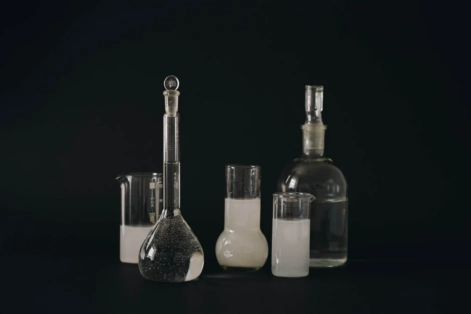
The single most useful artifact for a York buyer is a side-by-side table that can be lifted directly into a vendor brief. The values below combine published academic ranges, EPA categorical limits, and HydropureWater's integrated MBR system specifications for the 10–2,000 m³/day flow range (HydropureWater product catalog, 2026). Energy figures for submerged MBRs come in at 0.3–0.6 kW/m³ versus roughly 0.2–0.4 kW/m³ for CAS (per Water, 2018-08). Greenhouse gas emissions are close: 0.91 kgCO₂eq/m³ for MBR versus 0.85 kgCO₂eq/m³ for CAS at the plant-wide modeling benchmark (per ScienceDirect, 2019-11). Every plant engineer should run a calculation on their own flow and reuse targets before signing a PO to account for the trade-off between footprint/effluent quality and energy/membrane replacement cost.
| Parameter | MBR (submerged PVDF) | CAS (conventional) |
|---|---|---|
| Footprint | ~60% smaller than CAS at equal load (HydropureWater field data, 2026) | Larger; clarifier + aeration basin |
| Effluent TSS | <1 mg/L (HydropureWater product spec, 2026) | 10–30 mg/L typical |
| Effluent oil & grease | <5 mg/L with upstream DAF | 15–50 mg/L; upset-prone |
| Effluent total metals (Zn, Ni, Cu) | Meets 40 CFR 433 daily max in single stage | Often exceeds without polishing |
| MLSS | 8,000–12,000 mg/L | 2,000–4,000 mg/L |
| SRT | 20–60 days | 5–15 days |
| HRT | 4–12 hours | 6–24 hours |
| Sludge yield | 0.2–0.4 kg TSS/kg COD removed | 0.4–0.6 kg TSS/kg COD removed |
| Energy demand | 0.3–0.6 kW/m³ (per Water, 2018-08) | 0.2–0.4 kW/m³ |
| CAPEX | Higher (membranes, cassettes, blowers) | Lower; well-understood equipment |
| OPEX | Membrane replacement every 5–8 years; chemical CIP | Clarifier maintenance; sludge hauling |
| Sensitivity to oil upsets | High — oil must be removed upstream via a DAF system for oil and TSS removal | Moderate — clarifier tolerates spikes but effluent suffers |
| Plant-wide GHG (per ScienceDirect, 2019-11) | 0.91 kgCO₂eq/m³ | 0.85 kgCO₂eq/m³ |
| Membrane replacement interval | 5–8 years (PVDF flat sheet) | N/A |
For sites with limited pad space, the MBR footprint advantage is decisive—an integrated MBR system with submerged PVDF membranes typically fits inside a 40 ft container for flows up to ~250 m³/day, whereas a CAS train would need three or four separate basins. The energy penalty that pushes MBR operating costs above CAS enables the higher MLSS, longer SRT, and lower effluent TSS that determine whether the plant meets 40 CFR 433 in one pass or needs tertiary polishing.
Operating Realities: Fouling, Oil, and Hard Water in South-Central PA
MBR fouling is the primary operator-level issue that determines whether a York installation runs smoothly or requires frequent recovery cleanings. Academic work has quantified the dominant mechanism: biopolymer clusters (BPCs) accumulate on the membrane surface, where a 20–60% rise in BPC concentration in the mixed liquor raises the fouling rate by 120–300% (per PMC review, 2016-06). The operator sees this as a slow transmembrane pressure (TMP) creep followed by a sharp "TMP jump" once the biocake consolidates. York adds a local wrinkle: municipal water in south-central PA typically runs 100–200 mg/L as CaCO₃ hardness, and recirculation through an MBR can concentrate Ca²⁺ toward the 800 mg/L threshold above which inorganic scaling accelerates sharply (per PMC review, 2016-06). A DAF unit upstream of the MBR is mandatory for fabricated metals service, as free and emulsified oil must be removed before it contacts the membrane. A submerged MBR operating envelope worth quoting in a vendor spec is TMP 0.1–0.5 bar at flux 20–50 L/m²h, with energy demand 0.3–0.6 kW/m³ (per Water, 2018-08). While CAS avoids this specific fouling, it produces poor effluent during the same oil upsets, forcing a choice between manageable fouling via pretreatment and compliance excursions.
Compliance Map: EPA 40 CFR 413/433 and PA DEP Chapter 97
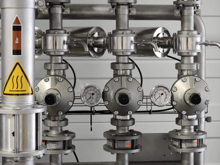
York fabricated metals plants are subject to a layered compliance picture. The federal floor is 40 CFR 413 (electroplating and metal finishing) and 40 CFR 433 (fabricated metals), which set categorical daily maximum and monthly average limits for total metals, oil and grease, and TSS. 40 CFR 433 sets oil and grease at 52 mg/L daily max and 26 mg/L monthly average, with total zinc at 1.48 mg/L daily max for the fabricated metals subcategory. PA DEP Chapter 97 overlays water-quality-based effluent limits (WQBELs) tied to the Susquehanna watershed, which can be tighter than the federal numbers when the receiving stream has low assimilative capacity. MBR effluent typically clears 40 CFR 433 oil and grease in a single stage with DAF upstream, while CAS usually requires post-polishing—sand filtration, cartridge filtration, or a membrane polish—to hit the same number reliably. A second compliance advantage is reuse: MBR permeate at <1 μm is suitable for rinsing-water reuse, which reduces raw-water draw and creates a permit-friendly narrative about water conservation that PA DEP reviewers respond to. CAS effluent at 10–30 mg/L TSS is not reusable without further treatment, yielding zero reuse value.
Decision Framework: When to Choose MBR, CAS, or Hybrid
The defensible rule for a York procurement manager is to match technology to site constraint rather than chasing the lowest CAPEX line item. Choose MBR when the site footprint is under ~0.5 acre, when discharge goes to a tight Susquehanna tributary with strict WQBELs, or when the plant plans to reuse rinsewater in a closed loop. Choose CAS retrofit when an existing aeration basin is structurally sound, when land is available for a new clarifier, and when discharge is to a POTW with conventional BOD/TSS limits. Choose a hybrid (CAS aeration followed by MBR polish on a sidestream) for high-flow plants that want reuse water from a partial stream without the full MBR energy bill. For modular deployments, DF series flat sheet membrane modules can be added in cassettes as flow grows, which preserves capital and matches the variability typical of York job shops. MBR earns its premium when footprint, effluent, or reuse drives the decision; CAS earns its place when existing assets and land are available and discharge limits allow conventional performance.
Frequently Asked Questions
What is the typical energy use of an MBR versus CAS for fabricated metals wastewater?
Submerged MBRs typically run 0.3–0.6 kW/m³, with most of that energy dedicated to membrane scouring air, while CAS aeration basins run 0.2–0.4 kW/m³ (per Water, 2018-08). The 30–50% energy premium reflects the membrane air scour needed to control fouling, not the biological oxygen demand. The trade-off is a smaller tank and reuse-quality effluent that offset energy costs in plants with high water-supply tariffs.
How much smaller is an MBR footprint compared to a CAS system of equal capacity?
An integrated MBR delivers approximately a 60% smaller footprint than a CAS train at equal organic load, because the secondary clarifier is eliminated and MLSS is held at 8,000–12,000 mg/L versus 2,000–4,000 mg/L (HydropureWater field data, 2026). For a 100 m³/day fabricated metals flow, a packaged MBR typically fits in a standard 40 ft skid where CAS would need separate aeration, clarification, and sludge-handling basins.
Which federal and state rules govern a York, PA fabricated metals discharge?
Discharge is governed by EPA 40 CFR 413 (metal finishing) or 40 CFR 433 (fabricated metals) categorical standards, with daily-maximum limits on oil and grease (52 mg/L), total zinc (1.48 mg/L), total nickel, and TSS. PA DEP Chapter 97 imposes additional water-quality-based effluent limits tied to the Susquehanna watershed, which can be stricter than the federal floor. An MBR with upstream DAF typically meets both layers in a single stage; CAS usually requires post-polishing.
Is oil and grease pretreatment required before an MBR in a stamping or machining facility?
Yes, pretreatment is required. Free and emulsified oil above 50 mg/L fouls MBR membranes irreversibly through biocake consolidation, so a DAF unit upstream of the MBR is standard practice for fabricated metals service. Without DAF, the operator faces rapid TMP rise, frequent chemical cleaning, and membrane replacement intervals that fall from the typical 5–8 years to under 3 years (per PMC review, 2016-06).