Why Ultrafiltration Is Now Standard in Airport Wastewater Reuse Trains
Hollow-fiber and flat-sheet ultrafiltration at 0.01–0.1 μm has become the default 2026 barrier between the DAF/MBR biological stage and the reverse osmosis polish that produces reuse water at airports. UF removes oil emulsions, colloidal TSS, and biomass carry-over that would otherwise foul the RO, and it operates reliably on equalized de-icing streams with COD swings from 400 mg/L to over 10,000 mg/L. The Beijing Capital International Airport reuse loop, treating 10,000 m³/day for toilet flushing, vehicle wash, irrigation, and cooling recirculation, is the longest-running precedent for this configuration (source: WaterWorld, 2007-10-04).
Beijing Capital handled roughly 50 million passengers per year at the time of the 2007 award, making it one of the world's top-10 airports and the largest in China; the inge AG dizzer® Multibore® UF system was specified as pretreatment to RO specifically because municipal-grade UF alone could not deliver the SDI <3 that the RO warranty demanded (source: WaterWorld, 2007-10-04). For a 2026 tender reviewer, that project remains the anchor precedent for an airport UF→RO reuse train and is the citation most likely to be accepted without challenge.
Airport wastewater is, in practice, four chemically distinct streams running through a single outfall: terminal sanitary sewage, apron and taxiway stormwater runoff, aircraft and hangar wash water, and seasonal de-icing fluid discharge. A single municipal-grade UF cannot serve all four without pretreatment — DAF must precede it for oil and grease, and equalization must precede biology for the glycol shock. The 2026 binding reuse targets for on-site non-potable service are BOD ≤10 mg/L, TSS ≤5 mg/L, NH4-N ≤1 mg/L, and E. coli ≤1 CFU/100 mL, and UF is the unit operation that delivers the TSS and turbidity envelope the RO must see (per HydropureWater field data, 2026). For a fuller breakdown of the four-stream chemistry, the airport wastewater characteristics and treatment 2026 process guide covers the loadings in more detail.
Where UF Sits in the 2026 Airport Treatment Train
The 2026 reference train at a greenfield or major-retrofit airport WWTP runs: rotary screening → DAF system ahead of the UF stage → 12–24 h equalization for de-icing → MBR → UF (polishing and RO protection) → industrial RO polish downstream of the UF stage → ClO2/UV disinfection. UF is positioned as a polishing barrier after the MBR, not as the primary biological separator, and its job is to drive SDI consistently below 3 — the threshold most RO membrane warranties require — while stripping residual colloidal TSS, oil carry-over, and biomass fragments that an MBR supernatant alone still releases.
DAF must precede UF because apron first-flush oil and grease runs 50–500 mg/L and peaks above 1,000 mg/L during rain events on a contaminated apron (per HydropureWater field data, 2026). Without DAF, oil emulsions blind the UF membrane surface and cut cleaning intervals from a typical 6 months down to about 6 weeks, which is uneconomic at any airport handling more than 100,000 aircraft movements per year. UF must precede RO because UF at 0.1 μm cuts silt density index to <3 and prevents colloidal fouling that no chemical pretreatment alone can eliminate; without that barrier, the RO sees a feed that fouls within weeks rather than months.
For airports with a documented AFFF history, or for hubs transitioning to fluorine-free firefighting foams, UF is no longer the final barrier for PFAS — dissolved short-chain PFAS such as PFBA and PFBS pass through a 0.1–0.4 μm membrane essentially untouched. A future NF/RO polish is the likely retrofit and is treated as a separate project, not a base-scope item (per HydropureWater field data, 2026). For greenfield design, integrating UF as a cassette retrofit on an existing MBR is the lowest-cost path; the limiting civil constraint is the aeration scour-air ratio, typically 0.3–0.5 Nm³/h per m² of installed membrane, which drives the MBR blower specification.
UF Design Parameters for Airport Service
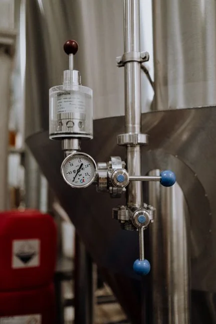
The 2026 UF design basis for an airport reuse train is a fixed set of parameters, all of which must be carried into the membrane-area calculation. Pore size sits in the 0.01–0.1 μm range; 0.1 μm is the airport norm because it delivers SDI <3 to the downstream RO at an acceptable flux and tolerates the backwash chemistry a glycol-bearing effluent demands. Membrane chemistry is PVDF for chemical and low-temperature tolerance; flat-sheet DF-series cassettes cover 80–225 m² per module at 32–135 m³/day per module, while hollow-fiber is the alternative when packing density is the priority (per HydropureWater catalog data, 2026).
| Parameter | 2026 Design Value (Airport Service) | Notes / Derating Trigger |
|---|---|---|
| Pore size | 0.1 μm (UF range 0.01–0.1 μm) | 0.1 μm is the airport norm; targets SDI <3 to RO |
| Membrane chemistry | PVDF (flat-sheet or hollow-fiber) | Specify for ≥5 °C mixed-liquor operation |
| Module area (DF-series flat-sheet) | 80–225 m² per cassette | 32–135 m³/day per module (HydropureWater catalog) |
| Design flux (gross, 20 °C) | 40–60 LMH | Net-to-gross factor typically 0.7 |
| Cold-climate flux (≤10 °C) | 28–42 LMH | ~30% derating below 10 °C mixed liquor |
| TMP envelope (service) | 0.3–1.0 bar | Sustained >1.2 bar triggers CEB |
| Backwash interval | Every 20–60 min | Permeate + air-scour; extend to 30 min during glycol events |
| CEB frequency | Weekly (NaOCl 200–500 mg/L free Cl₂) or citric acid | Daily CEB during COD >1,500 mg/L events |
| Air-scour ratio | 0.3–0.5 Nm³/h per m² membrane | Drives MBR blower sizing |
| Recovery per pass | 85–95% | Concentrate to sludge train or glycol-recovery side-stream |
The cold-climate derating is the single most-missed number in tender packages. A PVDF UF membrane derates by approximately 30% in flux below 10 °C mixed liquor, so the design flux at a northern hub drops from a 20 °C rating of 40–60 LMH down to 28–42 LMH at the worst-case winter temperature (per HydropureWater field data, 2026). The TMP envelope runs 0.3–1.0 bar in service; a sustained reading above 1.2 bar is the trigger for a chemically enhanced backwash with NaOCl at 200–500 mg/L free chlorine for organics, or citric acid for scale and oil. Backwash itself fires every 20–60 minutes using permeate plus air-scour, and recovery per pass sits at 85–95%, with the bleed routed either to the sludge train or to a glycol-recovery side-stream where seasonal volume exceeds 5,000 m³. Common operating pitfalls — TMP creep, flux loss, and CEB cycling — are catalogued in the UF system common problems and solutions 2026 guide.
Worked Sizing Example: 10,000 m³/day Northern-Hub Reuse Plant
Inputs for a representative northern-hub greenfield: design flow Q = 10,000 m³/day = 417 m³/h; winter mixed-liquor temperature 7 °C; target UF recovery 90%; design flux 35 LMH after the ~30% cold derating from a 50 LMH 20 °C basis; net-to-gross ratio 0.7 to back out dead modules, CEB downtime, and integrity-test hold steps.
- Required membrane area. Required area = Q / (flux × net-to-gross) = (417 m³/h × 1000) / (35 LMH × 0.7) ≈ 1,190 m² of installed membrane. Round to 1,200 m² to give a clean 5% margin against the temperature excursion.
- Module count. Using DF-series 0.1 μm PVDF flat-sheet UF cassettes at 150 m² per cassette, this works out to 8 cassettes, deployed on two parallel trains of 4 to give N+1 redundancy against cassette removal for CIP.
- Air-scour requirement. 1,200 m² × 0.4 Nm³/h·m² = 480 Nm³/h of scour air. A dedicated 15 kW blower is sized at 1.2× turndown to cover both membrane air-scour and the MBR cassette aeration demand without starving either consumer.
- Chemical cleaning regime. One CEB per week with 300 mg/L NaOCl for 30 minutes for organic fouling control, plus a quarterly CIP with citric acid at pH 2.5 to remove iron and oil scale that weekly CEB alone will not shift.
Output: the train produces RO-quality feed at SDI <2.5, ready for the industrial RO polish downstream of the UF stage that delivers BOD ≤10 mg/L, TSS ≤5 mg/L reuse water for toilet flush, irrigation, and aircraft wash. The biological MBR stage that protects the UF is sized in parallel using the integrated MBR treatment reference design, with the UF acting as the final suspended-solids barrier ahead of the RO high-pressure pump.
Operating UF Through the De-Icing Season
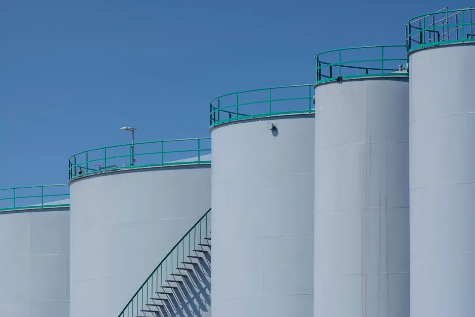
De-icing wastewater runs 10,000–50,000 mg/L COD, dominated by propylene or ethylene glycol, with BOD at roughly 50–60% of COD — a 25–125× swing above the dry-weather baseline (per HydropureWater field data, 2026). Equalization is non-negotiable: a 12–24 h HRT buffer tank damps the spike before it reaches the MBR/UF train, and without it, the biology trips daily from November through March and the UF sees fouling loads it was never sized for. At airports where seasonal de-icing volume exceeds 5,000 m³, a vacuum or membrane glycol-recovery unit upstream of equalization generates a resale credit of $0.50–1.50 per litre of recovered glycol and typically pays back the recovery skid in 2–4 winters (per HydropureWater field data, 2026).
During a glycol event the UF operating response is mechanical, not chemical: hold flux at the cold-derated design value rather than chasing the summer 50 LMH number, extend the backwash interval to 30 minutes to keep the membrane surface from blinding between cycles, and switch from weekly to daily CEB with 300 mg/L NaOCl until influent COD drops back below 1,500 mg/L. The cold-climate module specification is the other place a tender quietly fails: insist on PVDF rated for ≥5 °C mixed-liquor operation and verify in writing that the vendor's flux warranty applies at the project's design winter temperature, not at 20 °C. Module-area math built on a 20 °C flux at a hub that sees −10 °C ambient will under-size the cassette count by roughly 30%.
Compliance and Reuse Pathways for 2026
The 2026 regulatory anchors governing an airport UF design are four documents, and the tender reviewer will expect each one cited by name. EU UWWTD 91/271/EEC sets 95th-percentile discharge limits of BOD ≤25 mg/L, COD ≤125 mg/L, and TSS ≤35 mg/L for any terminal discharging above 2,000 p.e. — the DAF + MBR + UF train hits these with margin (per HydropureWater field data, 2026). ICAO Annex 14 Vol. I Attachment C overlays airport-specific guidance but defers numeric limits to local regulation; the standard practice is to adopt the stricter of the two. In the US, cold-climate states (Minnesota, Michigan, New York) are tightening glycol-specific COD caps and pushing older equalization-only designs toward side-stream glycol recovery and RO polish. China GB 8978 applies to designated airport discharge zones with COD ≤60–100 mg/L, BOD ≤20–30 mg/L, and oil & grease ≤5 mg/L, which means DAF must polish O&G to <5 mg/L before the wastewater ever reaches the UF.
For on-site non-potable reuse — toilet flush, irrigation, aircraft wash feed — the binding envelope is BOD ≤10 mg/L, TSS ≤5 mg/L, NH4-N ≤1 mg/L, and E. coli ≤1 CFU/100 mL, and only an MBR + UF + RO + ClO2/UV chain reliably hits all four numbers at the same time. The reuse design also has to crosswalk to drinking-water criteria for any human-contact endpoint, which is covered in the drinking water treatment plant design criteria 2026 engineering specs reference.
Frequently Asked Questions
What pore size and rejection targets should a 2026 airport UF hit?
Specify 0.1 μm PVDF UF. The unit operation should deliver SDI <3 (typically <2.5 in practice) to the downstream RO, turbidity ≤0.1 NTU, TSS ≤1 mg/L, oil & grease <5 mg/L after a properly sized DAF upstream, and ≥4 log removal of colloidal carry-over. Anything coarser than 0.1 μm compromises the RO warranty envelope; anything finer than 0.01 μm sacrifices flux without a meaningful gain in SDI.
Can an MBR alone replace UF in an airport reuse train?
No. An MBR delivers BOD ≤10 mg/L and most of the TSS removal, but MBR supernatant still carries colloidal solids, oil micro-emulsions, and biomass fragments that push SDI to 4–6 — above the <3 threshold RO membrane warranties require. The UF stage is the unit operation that closes the SDI gap, and removing it shortens RO cleaning intervals from months to weeks at an airport.
Where does UF end and NF/RO become mandatory for PFAS?
UF does not remove dissolved short-chain PFAS such as PFBA and PFBS — those pass through a 0.1 μm membrane essentially untouched. For any hub with an AFFF history, or any project targeting the tightening 2026 state-level PFAS limits in the US, NF or RO is required downstream of the MBR/UF pair, with concentrate handling treated as a separate retrofit rather than base scope.
Is the 2007 Beijing Capital precedent still defensible in a 2026 tender?
Yes. The configuration — UF as RO pretreatment, 10,000 m³/day reuse for toilet flush, vehicle wash, irrigation, and cooling recirculation — has been operating continuously for nearly two decades, was extended with a second inge UF replacement order for the upgraded system, and remains the longest-running airport UF→RO reuse precedent a tender reviewer will recognise (source: WaterWorld, 2007-10-04; Mark Allen Group, 2020).