

What a DAF System Process Flow Diagram Shows
A DAF system process flow diagram traces wastewater from influent screening through coagulation, flocculation, and a flotation cell where micro-bubbles lift suspended solids, FOG, and colloids to the surface for skimming. The recycle loop pressurizes 15–30% of clarified effluent at 4–6 bar in a saturation tank, then injects it into the contact zone. Air-to-solids ratio (typically 0.01–0.05) governs dissolved-air mass and is the principal design lever.
Every industrial DAF system process flow diagram contains five functional blocks regardless of vendor or capacity: influent equalization, coagulation/flocculation, the flotation cell with skimmer, the clarified-effluent outlet, and the recycle saturation loop. The PFD is the precursor to a P&ID — it shows unit operations and stream connections, while the P&ID adds instruments, valves, and control loops that a constructor can actually build from. In recycle-pressurization (the standard industrial configuration), only 15–30% of clarified effluent is pressurized, so chemical flocs formed in the unpressurized stream never see the recycle pump or pressure-letdown valve; floc integrity is preserved. Direct pressurization, by contrast, sends the entire forward flow through the pump and release valve, which shears flocs and is generally avoided for industrial wastewater (per ScienceDirect topic page on dissolved air flotation, 2025).
Block 1 — Influent Feed and Coagulation/Flocculation
Influent enters an equalization basin sized for 4–8 hours of hydraulic retention to dampen flow and load swings, then flows through a static mixer or rapid-mix chamber where coagulant — typically alum at 50–150 mg/L, PAC at 20–80 mg/L, or ferric chloride at 30–100 mg/L — is dosed to neutralize the negative surface charge on colloidal solids. Charge neutralization is the prerequisite for bubble attachment: a bubble will not adhere to a particle whose surface charge repels it. Coagulant demand is a function of influent turbidity and is normally trimmed in the field by jar testing before being locked into the PLC.
Flocculant (typically anionic polyacrylamide, 0.5–3 mg/L active) is added in a downstream slow-mix flocculation tank with HRT 10–20 minutes at a velocity gradient G of 50–100 s⁻¹ to build pin floc that bubbles can attach to. Residence times below 10 minutes produce fragile floc that fragments in the contact zone; residence times above 25 minutes risk floc settling before reaching the cell. Chemical dosing is PLC-controlled, so for the reader's PFD, show a coagulant dosing skid and flocculant dosing skid as side streams into the main line, with the polymer make-up unit feeding the flocculant line. For a packaged chemical skid, see the automatic chemical dosing system we supply for flows 5–500 m³/h.
Block 2 — Flotation Cell and the Contact Zone
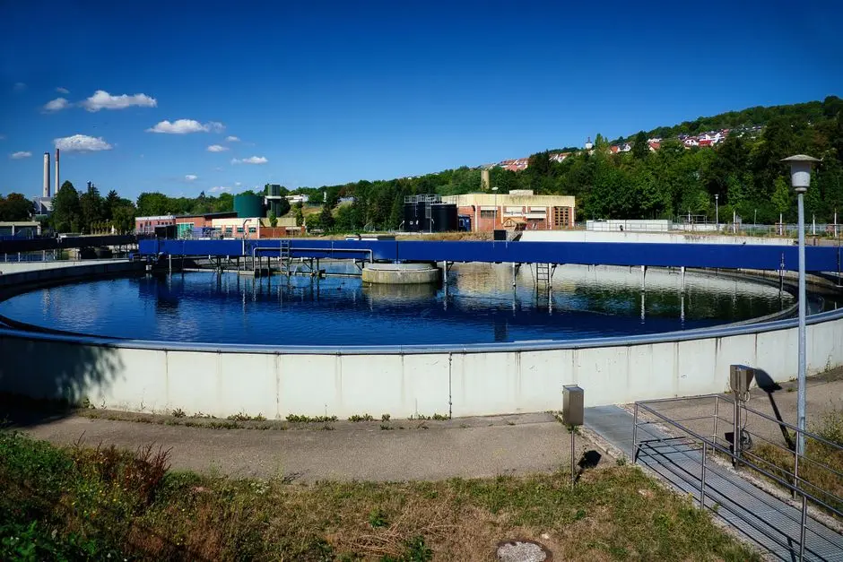
Pressurized recycle is released through needle valves or specially designed hydraulic nozzles into the contact zone at the inlet of the flotation cell, generating 10–100 µm micro-bubbles (per ScienceDirect, 2025) that attach to floc particles and lower their effective density below that of water. The contact zone is separated from the separation zone by a submerged baffle; contact zone HRT is typically 1–3 minutes and is sized for rapid bubble-floc collision, while separation zone HRT is 10–30 minutes depending on hydraulic loading and target effluent TSS. The hydraulic residence split is the single most often mis-sized parameter on vendor submittals — reviewers should confirm both numbers against the design basis.
The float layer, typically 50–150 mm thick, is scraped by a surface skimmer (scoop, paddle, or belt type) into a sludge hopper at the upstream end of the cell. Skimmer rotational speed is 0.5–2 rpm to avoid re-entraining float; surface overflow rate is held below 20 m/h. Bottom sludge, where particles are denser than water and drop out, collects in a conical bottom for separate blowdown if the influent carries high specific-gravity grit. The cell body itself, including the contact-zone baffle geometry, is part of the dissolved air flotation system design and is factory-fabricated in carbon steel with epoxy lining or in 304/316 stainless for corrosive streams.
Block 3 — Pressurized Recycle and Saturation Tank
The recycle loop is the heart of any DAF PFD and where most of the engineering rigor should be applied. A portion of clarified effluent — typically 15–30% of forward flow, with 20% being a common design point — is diverted from the clarified-effluent launder back to the saturation tank. An air compressor injects compressed air at 4–6 bar (60–90 psi) into the packed or baffled saturation vessel; dissolved air at 5 bar exceeds atmospheric equilibrium by roughly 4–5×, which is the driving force for bubble nucleation when pressure is released at the contact zone. Typical saturation HRT is 30–90 seconds at design flow, with a 3–5 bar pressure drop across the outlet valve generating the micro-bubble cloud.
Use the recycle-pump HP equation to size the pump motor:
HP = (Q × ρ × H) / (550 × pump efficiency)
where Q is the recycle flow (ft³/s), ρ is the specific weight of water (62.4 lb/ft³), H is the pressure head against which the pump is pumping in feet of water (1 bar ≈ 33.9 ft of water), and pump efficiency is typically 0.65–0.80. HP scales linearly with pressure and inversely with flow rate — so doubling the saturation pressure doubles the pump HP at fixed recycle, while halving the recycle percentage halves it (per ScienceDirect, 2025). The outlet valve from the saturation tank simultaneously regulates three variables: tank pressure, recycle flow, and retention time — so the valve trim, characterized for the full operating range, is a critical instrument spec on the P&ID. For a deeper treatment of how these variables interact in the field, the DAF system troubleshooting guide covers the failure modes directly tied to saturation-tank pressure drift.
Block 4 — Clarified Effluent and Sludge Outlets
Clarified effluent overflows a launder weir at the downstream end of the cell and flows by gravity to downstream biological treatment — typically an MBR or SBR — or to reuse polishing (multi-media filter followed by RO for industrial reuse). The effluent launder should be level within ±3 mm across its length; any slope bias creates a hydraulic short-circuit and reduces effective cell volume. Float sludge is scraped to a sludge hopper and pumped to a sludge holding tank; the float is typically 3–6% dry solids and reports to a plate and frame filter press for final dewatering to 22–28% cake solids.
Draw both outlets on the PFD with a flow transmitter (FIT) on the effluent line, a turbidity meter (AIT) for performance monitoring, and a level switch (LSL/LSH) on the sludge hopper to prevent overflow. The table below summarizes the key specification parameters for these two outlet streams.
| Outlet Stream | Typical Parameter | Range / Value | Notes |
|---|---|---|---|
| Clarified effluent | TSS removal | 70–95% | Depends on influent TSS and A/S ratio |
| Clarified effluent | Turbidity | 1–15 NTU | Soft performance indicator |
| Clarified effluent | Flow instrument | FIT, mag meter | ±1% accuracy, 4–20 mA output |
| Float sludge | Dry solids | 3–6% DS | Reports to filter press for dewatering |
| Float sludge | Volume reduction | ~95% water removed | Before downstream dewatering |
| Float sludge | Level control | LSL / LSH on hopper | Prevents overflow and pump cavitation |
Recycle vs Direct Pressurization: Choosing the Right Flow Path
Direct pressurization sends the entire forward flow through the recycle pump and pressure-release valve; recycle pressurization pressurizes only 15–30% of clarified effluent. The trade-off is floc integrity versus hydraulic simplicity. In direct pressurization, the pump and pressure-letdown valve shear chemical flocs, which significantly reduces removal efficiency for floc-bound contaminants — and is generally avoided for industrial wastewater (per ScienceDirect topic page on DAF, 2025). Recycle pressurization preserves floc by keeping the chemical-conditioning stream at atmospheric pressure, at the cost of an additional recycle pump, saturation tank, and air compressor.
The selection logic is straightforward: if the influent requires coagulant or flocculant to achieve target TSS, specify recycle pressurization; if the influent is already low-turbidity and particulate-dominated (e.g., a sand-laden wash water), direct pressurization may be acceptable and reduces capex. The table below summarizes the comparison for a design memo.
| Parameter | Recycle Pressurization | Direct Pressurization |
|---|---|---|
| Flow pressurized | 15–30% of forward flow | 100% of forward flow |
| Floc integrity | Preserved (floc not pumped) | Sheared at pump and letdown valve |
| Equipment count | Saturation tank, recycle pump, air compressor, needle valves | Forward pump, pressure-release valve, air compressor |
| Saturation pressure | 4–6 bar | 4–6 bar |
| Pump HP scaling | HP ∝ recycle% × pressure | HP ∝ 100% × pressure (much higher) |
| Typical application | Industrial wastewater with chemical conditioning | Low-turbidity particulate streams without flocculation |
From PFD to P&ID: Instrumentation on a DAF Flow
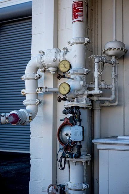
Critical instruments on a DAF P&ID fall into four control loops. The pressure control loop uses a pressure transmitter (PT) on the saturation tank to modulate the outlet pressure-control valve (PCV) and maintain 4–6 bar. The recycle flow loop uses a mag-meter flow transmitter (FIT) on the recycle line to trim the recycle rate to the 15–30% target, typically through a VFD on the recycle pump rather than a throttling valve to save energy. The cell level loop uses a level transmitter (LT) on the flotation cell to throttle the influent inlet valve and prevent cell overflow during hydraulic surges. The sludge loop uses a level switch (LSH) on the sludge hopper to start and stop the sludge transfer pump, and a consistence meter where cake-solids targets are tight.
A turbidity meter on the clarified-effluent line is a soft performance indicator — it is not part of a closed control loop but is logged for trend analysis and is invaluable during commissioning and optimization. For procurement engineers comparing scopes of supply, the best DAF unit for industrial wastewater 2026 guide maps these instrument loops against typical vendor submittals. For alternative separation technologies, the DAF vs clarifier comparison covers when DAF is the right choice over a conventional clarifier.
Key Parameters to Annotate on the Diagram
The single most copy-pasted element of any DAF PFD article is the consolidated parameter table. Lay these values on the diagram as inline callouts so a reviewer reading the flowsheet sees the operating envelope without flipping to a datasheet. The table below is sized to drop directly into a design memo.
| Parameter | Units | Typical Range | Source |
|---|---|---|---|
| Forward flow | m³/h | Per design basis (5–500 typical) | Project specification |
| Recycle flow | % of forward | 15–30% (20% design point) | ScienceDirect, 2025 |
| Saturation pressure | bar (g) | 4–6 bar (60–90 psi) | ScienceDirect, 2025 |
| Air-to-solids ratio (A/S) | dimensionless | 0.01–0.05 | ScienceDirect, 2025 |
| Contact-zone HRT | minutes | 1–3 min | Engineering standard |
| Separation-zone HRT | minutes | 10–30 min | Engineering standard |
| Flocculation HRT | minutes | 10–20 min | Engineering standard |
| Micro-bubble diameter | µm | 10–100 µm | ScienceDirect, 2025 |
| Float sludge dry solids | % DS | 3–6% | Engineering standard |
| Recycle pump HP | HP | HP = (Q × ρ × H) / (550 × η) | ScienceDirect, 2025 |
| Coagulant dose | mg/L | 20–150 (alum/PAC/FeCl₃) | Project specification |
| Flocculant dose | mg/L active | 0.5–3 (anionic PAM) | Project specification |
Frequently Asked Questions
What is the typical recycle ratio in a DAF system?
The recycle ratio in an industrial DAF system is typically 15–30% of the forward flow, with 20% being a common design point. Lower recycle reduces pump HP but limits the dissolved-air mass available for bubble-particle attachment; higher recycle increases operating cost without proportional TSS-removal gains (per ScienceDirect, 2025).
What pressure should the saturation tank operate at?
Saturation tank pressure is typically 4–6 bar (60–90 psi). At 5 bar, dissolved air exceeds atmospheric equilibrium by roughly 4–5×, which is the driving force for micro-bubble nucleation when pressure is released at the contact-zone nozzles.
What is the air-to-solids ratio in dissolved air flotation?
The air-to-solids ratio (A/S) is the dimensionless ratio of dissolved-air mass to suspended-solids mass and is the principal design lever in a DAF system. Typical values are 0.01–0.05; values below 0.01 produce under-aerated float and high residual TSS, while values above 0.05 waste compressor energy without removing additional solids (per ScienceDirect, 2025).
Why is recycle pressurization preferred over direct pressurization?
Recycle pressurization keeps the chemically conditioned floc at atmospheric pressure, so flocs are not sheared by the recycle pump or pressure-letdown valve. Direct pressurization sends the entire forward flow through the pump and release valve, which shears flocs and is generally avoided for industrial wastewater where floc-bound contaminant removal is required (per ScienceDirect topic page on DAF, 2025).
How is the recycle pump sized on a DAF PFD?
Recycle pump HP is calculated as HP = (Q × ρ × H) / (550 × pump efficiency), where Q is the recycle flow in ft³/s, ρ is the specific weight of water (62.4 lb/ft³), H is the saturation tank pressure in feet of water (1 bar ≈ 33.9 ft), and pump efficiency is typically 0.65–0.80. HP scales linearly with both pressure and flow rate (per ScienceDirect, 2025).