
Why QC Lab Sink Wastewater Fails an Unprotected MBBR
A pharmaceutical QC lab discharging 3–15 m³/day of sink waste is one of the worst feeds an MBBR can receive without a guard envelope: pH swings between 1 and 13 within a single shift, COD between 800 and 8,000 mg/L depending on whether a titration series or an HPLC mobile-phase rinse just hit the drain, and intermittent slugs of acetonitrile, methanol, acetone, sulfuric acid, or sodium hydroxide. None of these match the steady, biodegradable, near-neutral profile that moving-bed biofilm carriers are designed to metabolize.
The toxicity mechanism is direct. Acetonitrile and methanol at concentrations above roughly 1% v/v in the reactor bulk act as cell-membrane solvents and strip established biofilm from carrier surfaces; pH below 6 or above 9 collapses nitrifier activity because free ammonia (NH₃) and free nitrous acid (FNA) shift out of the band where Nitrosomonas and Nitrobacter operate, with measurable inhibition above 10 mg/L NH₃ in pharmaceutical matrices. A 2025 MDPI A2O-MBBR study on leachate pretreatment showed that an upstream physico-chemical step delivered 49.0% COD removal, 4.8% BOD₅ removal, and 11.2% NH₄⁺-N removal before the biological stage — the same logic applies to lab sink streams, where a properly sized pretreatment train is what makes the downstream MBBR viable rather than optional. Unprotected carriers on raw lab sink feed lose 40–60% of colonization within 2–4 weeks (HydropureWater field data, 2026), and the failure usually presents as foam, carrier washout, and a sudden drop in effluent ammonia. The remedy is a five-step pretreatment train that the engineer specifies before the MBBR ever sees a drop of sink water — a control point also reinforced in the companion MBR configuration guide for QC lab sinks.
Pretreatment Train Overview: Five Unit Operations Before MBBR
The pretreatment train runs in this fixed order on the P&ID: (1) fine screening, (2) flow and pH equalization, (3) oil, grease, and solvent removal, (4) pH neutralization with automatic chemical dosing, and (5) toxic-load buffering with a slug-catch safeguard. Each step exists to neutralize one specific failure mode the MBBR cannot survive — screening prevents carrier bridging, equalization dampens diurnal shocks, DAF or stripping removes oil and volatile solvents, dosing holds pH in the 6.0–9.0 nitrification band, and the slug-catch chamber diverts any batch that exceeds conductivity, TOC, or pH setpoints back to the equalization basin.
For the typical 5–10 m³/day lab flow range, the entire train should be skid-mounted on a single 304/316L stainless frame with a common control panel, because field-erected concrete tanks are over-spec and over-budget at this scale. The MBBR inlet boundary is fixed at the outlet of the slug-catch chamber: pH 6.0–9.0, COD ≤1,500 mg/L (24-h composite), oil <20 mg/L, free NH₃ <5 mg/L, total residual solvent <0.1% v/v. Every parameter downstream of the train is referenced to that boundary, which is why a consolidated spec table sits at the end of this article for direct lift into a design basis or RFQ.
Step 1: Fine Screening to Protect MBBR Carriers
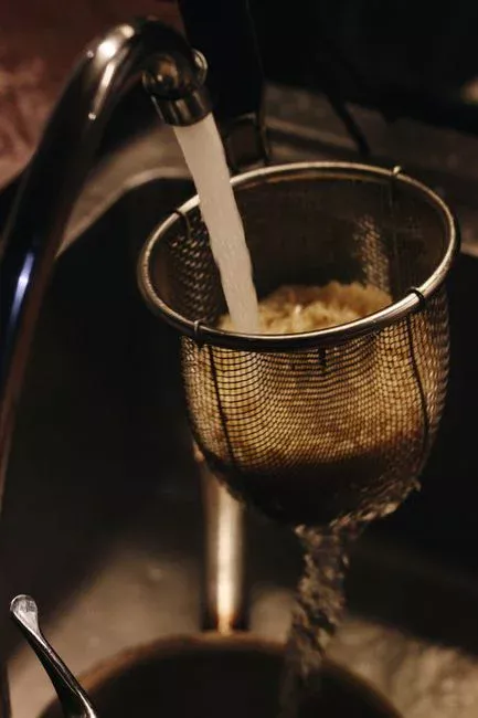
Lab sink streams carry wipes, broken glass vials, pipette tips, and septa that municipal bar screens at 3–5 mm openings pass straight through; any fragment larger than the carrier slot (~10–15 mm for typical Kaldnes-type media) can bridge across multiple carriers and create a debris mat that shadows the biofilm underneath. Specify 1–2 mm perforated openings for QC lab sink streams — finer than municipal practice and essential at this scale.
Construction material is 316L stainless steel for solvent compatibility; 304 stainless suffers pitting attack from chloride-bearing mobile-phase buffers and from routine 1–5% HCl and HNO₃ sink rinses. For 3–15 m³/day flows with low head-loss tolerance, a static wedge-wire screen with an automated brush cleaner is the simplest fit; for flows above ~10 m³/day or where wipe loadings are heavy, a drum-type GX Series rotary mechanical bar screen running at 4–8 rpm gives continuous self-cleaning without operator intervention. The failure mode this prevents is twofold: carrier bridging (mechanical) and biofilm shadowing (biological), where anaerobic zones under a debris mat begin to slough and seed the bulk liquor with detached biomass that drives downstream turbidity and fouling.
Step 2: Flow and pH Equalization Tank Sizing
Equalization is the single most important tank in the train, because it is the only step that buffers the MBBR against the diurnal titrant dumps and solvent rinses that define a QC lab shift pattern. Specify 8–24 h HRT based on operating schedule: 8 h for steady 3-shift labs where flow is roughly continuous, 24 h for single-shift QC benches where the entire daily load is dumped in a 4–6 h window. The sizing equation is straightforward:
Volume (m³) = Average daily flow (m³/d) × HRT (h) / 24
For a 10 m³/d lab with 16 h HRT, that gives 6.7 m³ of working volume plus 20% freeboard for foam and surge. A single submersible mixer at 3–5 W/m³ (typical for wastewater EQ basins) is required to keep settleable solids in suspension and to homogenize pH; without mixing, pH stratification inside the tank produces pockets as low as 1.5 and as high as 12.5 that pass through the neutralization reactor faster than the pH probe can respond.
EQ alone dampens a raw pH 1–13 swing to roughly pH 4–10, which is not enough for the MBBR but is enough to drop the peak acid or base loading on the downstream dosing system by an order of magnitude. The target post-EQ variability is COD variance reduced by ≥60% and pH band tightened to ±2 units, both of which are auditable in a 24-h composite sample. The table below summarizes the EQ sizing rules for the three most common lab flow ranges:
| Lab flow (m³/d) | Shift pattern | HRT (h) | EQ volume (m³) | Mixer power (W/m³) |
|---|---|---|---|---|
| 3–5 | Single shift, batch titrant dumps | 20–24 | 2.5–5.0 | 3–5 |
| 5–10 | Two-shift, intermittent HPLC rinses | 12–16 | 2.5–6.7 | 3–5 |
| 10–15 | Three-shift, near-continuous | 8–10 | 3.3–6.3 | 4–5 |
Step 3: Oil, Grease, and Solvent Removal
The third step splits on contaminant type. For oil, grease, and surfactant-laden samples (HPLC column flushes, extraction solvent residues, soap-stabilized samples), specify a dissolved air flotation system with 20–80 µm micro-bubbles, hydraulic surface loading of 5–15 m/h, and a target effluent oil concentration below 20 mg/L — well under the 50–100 mg/L threshold that begins to coat MBBR carriers and block oxygen transfer. DAF also strips a fraction of the dissolved volatile solvents as a side benefit, but it should not be relied on as the sole solvent-removal step.
For volatile solvents — acetonitrile (bp 82 °C), methanol (bp 65 °C), acetone (bp 56 °C), and ethanol — the primary unit is a packed-tower air stripper with an air-to-water ratio of 30:1 to 60:1 and 1.5–2.5 m of 50–75 mm polypropylene pall rings. At these ratios, removal efficiencies of 60–90% per pass are typical for the solvents listed, dropping bulk-phase solvent concentration below the 0.1% v/v threshold that begins to inhibit nitrification. The MDPI A2O-MBBR work is the parallel case here: upstream pretreatment delivered 49.0% COD removal before the biological stage, and the same principle — knock down the toxic load before biology sees it — is what allows a small MBBR to handle a toxic feed.
One operational note that often gets missed in design: HPLC mobile-phase waste should be segregated to a dedicated solvent-collection drum and disposed as hazardous waste, not sent to the lab sink drain. The pretreatment train can handle a slug; it cannot handle the daily throughput of a busy chromatography group if all of it is routed through the sink.
Step 4: pH Neutralization with Automatic Chemical Dosing
Even after 16–24 h of equalization, pH still drifts outside the biofilm-safe band, so the fourth step is active neutralization. Specify a PLC-controlled automatic chemical dosing system with two metering pumps drawing from a 10–20% NaOH drum and a 10–15% H₂SO₄ or HCl drum, controlled by an inline pH probe in a two-stage CSTR arrangement. Two stages in series prevent the pH overshoot that single-tank designs produce when the controller "chases" a moving setpoint: stage 1 takes the bulk of the acid or base dose, stage 1 effluent feeds stage 2, and stage 2 trim dosing holds pH in the target band.
Hydraulic residence in the neutralization reactor should be 15–30 min total (split roughly 60/40 between the two stages) to give the controller time to react to a slug before the water reaches the MBBR. The biofilm target band at the MBBR inlet is pH 6.0–9.0; below pH 6.5, nitrifier activity in pharmaceutical wastewater falls below 50% of maximum (per general MBBR design practice for high-strength industrial feeds), and above pH 9.0, free NH₃ rises past 10 mg/L at typical 25 °C operating temperature and begins to inhibit the same nitrifiers. The failure mode this prevents is a nitrification collapse that typically presents 5–10 days after a pH excursion as rising effluent ammonia and a shift in carrier color from healthy brown to pale grey.
Foaming from FOG and surfactant carryover is a secondary failure mode and is why DAF sits upstream of the neutralization reactor in the P&ID — by the time the water reaches the dosing stage, oil and grease should already be below 20 mg/L.
Step 5: Toxic Load Buffering and Slug-Catch Protection
The fifth and final step is the operational safeguard that turns the MBBR from a fragile biofilm into a robust biological stage. Install a slug-catch chamber immediately upstream of the MBBR feed pump, fitted with three inline sensors: a pH probe, a conductivity probe, and a TOC analyzer (or a UV₂₅₄ probe as a surrogate where a full TOC is not justified at this scale). The chamber is small — typically 0.5–1.0 m³ working volume, sized for 5–10 min of peak flow — and its sole function is to act as a final diversion point.
Alarm setpoints are hard-coded and should be reviewed during commissioning: pH below 5 or above 10, conductivity above 8,000 µS/cm, or TOC above 2,000 mg/L triggers a divert valve that routes the batch back to the EQ basin. A 1–2 m³ emergency holding tank downstream of the divert valve captures the slug for slow re-feed into the EQ basin over the next 8–24 h, rather than sending the entire concentrated batch back through the plant in one pulse. This is the difference between a one-day upset the operator can manage and a multi-week biofilm recovery that takes the MBBR offline. The slug-catch chamber is also the right place to locate the MBBR feed sampling port, because any sample taken downstream of diversion reflects the actual feed the biofilm is seeing.
Consolidated Pretreatment Train Specification Table
The table below is the single artifact a process engineer can lift into a design basis document or an RFQ package without rewriting. Every row is referenced to the MBBR inlet boundary, which is the design handoff point to the downstream biological stage.
| Step | Unit operation | Key parameter | Design value | Basis / source |
|---|---|---|---|---|
| 1 | Fine screening | Opening size | 1–2 mm perforated, 316L SS | Glass and pipette fragment control |
| 2 | Flow / pH equalization | HRT | 8–24 h, sized by shift pattern | HydropureWater field data, 2026 |
| 3a | DAF (oil / FOG) | Surface loading; effluent oil | 5–15 m/h; <20 mg/L | MBBR carrier oxygen-transfer limit |
| 3b | Packed-tower air stripping (solvents) | Air:water ratio | 30:1 to 60:1 | Acetonitrile/methanol removal 60–90% |
| 4 | pH neutralization, two-stage CSTR | HRT; target pH | 15–30 min; 6.0–9.0 | Nitrifier activity threshold |
| 5 | Slug-catch chamber + divert | Alarm setpoints | pH <5 / >10; cond. >8,000 µS/cm; TOC >2,000 mg/L | MBBR inhibition limits |
| MBBR inlet boundary | pH; COD; oil; free NH₃; solvent | 6.0–9.0; ≤1,500 mg/L; <20 mg/L; <5 mg/L; <0.1% v/v | Design handoff to MBBR spec | |
Frequently Asked Questions
What is the minimum pretreatment a QC lab sink needs before an MBBR?
At minimum: fine screening at 1–2 mm, an 8–24 h equalization basin with mixing, oil and solvent removal (DAF and/or air stripping), PLC-controlled pH neutralization to a 6.0–9.0 band, and a slug-catch chamber with divert on pH, conductivity, and TOC setpoints. Skipping any one of these steps risks 40–60% carrier colonization loss within 2–4 weeks on raw lab sink feed (HydropureWater field data, 2026).
How do I size the equalization tank for a pharmaceutical QC lab?
Use Volume (m³) = Average daily flow (m³/d) × HRT (h) / 24. For a single-shift lab with batch titrant dumps, use 20–24 h HRT; for a 3-shift continuous lab, 8–10 h is sufficient. A 10 m³/d lab at 16 h HRT requires 6.7 m³ of working volume plus 20% freeboard, with a submersible mixer at 3–5 W/m³.
Can HPLC mobile-phase solvents (acetonitrile, methanol) go down the lab sink?
They can, but should not in volume. A packed-tower air stripper at 30:1 to 60:1 air-to-water ratio removes 60–90% of acetonitrile, methanol, and acetone per pass and drops bulk solvent below the 0.1% v/v threshold that inhibits nitrification. For high-throughput chromatography groups, segregate mobile-phase waste to a dedicated collection drum for hazardous-waste disposal rather than routing it through the sink.
What pH band does an MBBR need at the inlet to keep nitrification stable?
Hold MBBR inlet pH between 6.0 and 9.0. Below 6.5, nitrifier activity in pharmaceutical wastewater falls below 50% of maximum; above 9.0, free NH₃ exceeds 10 mg/L at 25 °C and inhibits the same organisms. A two-stage CSTR with 15–30 min total HRT and PLC-controlled acid/base dosing is the standard configuration.
Where can I find the MBBR sizing that comes after this pretreatment train?
The companion MBR configuration guide for QC lab sinks picks up at the MBBR inlet boundary defined in the consolidated spec table and covers carrier fill fraction, HRT, and aeration sizing for the same 3–15 m³/day flow range.