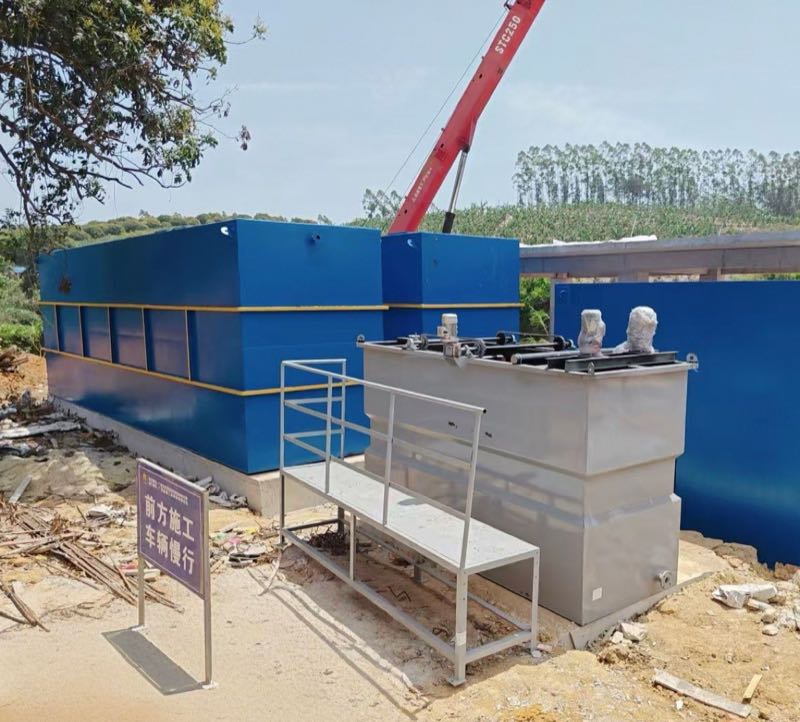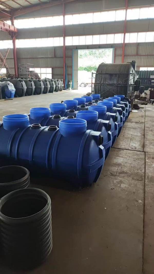
Why Wastewater Treatment System Sizing Matters
Wastewater treatment system sizing sets hydraulic capacity and organic load so a plant meets permit limits under average and peak conditions. Designers size on peak flow, BOD loading, and retention time, not average daily flow alone. Undersizing causes overflows and violations; oversizing raises capital cost and can destabilize biology when actual load stays low for years.
Proper wastewater treatment system sizing balances average and peak conditions against discharge limits.NYSDEC’s Design Standards for Intermediate Sized Wastewater Treatment Systems (March 5, 2014) remain New York’s governing reference for intermediate systems. New York City watershed rules amended February 28, 2025 still cite that 2014 manual.
A food processing plant in upstate New York faced $85,000 in NYSDEC fines after its undersized activated sludge system failed to handle peak BOD loads during harvest season. The plant’s 250,000 GPD system was designed for average flows—but when production spiked, untreated effluent overflowed into a nearby trout stream, violating SPDES permit limits of 30 mg/L BOD. Undersizing risks environmental violations, operational shutdowns, and costly retrofits. Oversizing wastes capital on unused capacity—studies show 30-40% of municipal treatment plants operate at less than 60% design flow for the first decade. Capacity calculation must account for three core factors:
| Sizing Factor | Industrial Impact | Municipal Impact | Regulatory Standard |
|---|---|---|---|
| Peak Flow Rate | Batch discharges from CIP systems can triple average flows | Infiltration/inflow during storms may increase flows by 200% | NYSDOH requires 150% of average daily flow for design (2014 Design Standards, §3.2) |
| BOD Loading Rate | Dairy plants average 1,500 mg/L BOD vs. 250 mg/L for municipal | Combined sewer overflows may spike BOD to 500 mg/L | EPA limits secondary treatment to 30 mg/L BOD (40 CFR 133.102) |
| Retention Time | DAF systems require 3-5 minutes for 90% TSS removal | Activated sludge needs 4-8 hours for nitrification | NYDEC mandates 24-hour retention for Class I systems (Design Standards, §5.3) |
For industrial applications, wastewater retention time and hydraulic loading rates dictate equipment selection. A meat processing facility might require a DAF system sized for 500 GPM peak flow with 4-minute retention. A municipal plant serving 10,000 people would need a 1.5 MGD activated sludge system with 6-hour detention. Both must comply with industrial effluent standards—whether EPA categorical pretreatment standards or NYSDEC SPDES permit limits. Mis-sizing drives permit risk and energy waste; a data-driven approach integrates flow metering, load testing, and regulatory requirements before equipment is ordered.
Step 1: Determine Your Wastewater Flow Rate (Peak vs. Average)
Accurate capacity work begins with calculating the facility’s flow rate—both average and peak. Undersizing leads to regulatory violations under NYSDEC’s Design Standards for Intermediate Sized Wastewater Treatment Systems, while oversizing wastes capital and energy. Industrial and municipal applications demand distinct approaches to capacity calculation.
How do you size a plant for 1 million people?
A plant for 1,000,000 people is sized from per-capita flow, then multiplied by a peaking factor for wet-weather and diurnal peaks. Using 80 gallons per capita per day (gpcd) average flow yields about 80 MGD average daily flow (1,000,000 × 80 gpcd). Applying a 2.5–4.0× peak hourly multiplier (NYSDEC, 2014) gives roughly 200–320 MGD peak hydraulic capacity before I/I allowances. Always confirm local peaking curves and industrial contributions before locking tank volumes.
Municipal Systems: Population-Based Flow Rates
For municipal sewage treatment plants, flow rates are derived from population data and per-capita water usage. The EPA’s Wastewater Technology Fact Sheet (EPA 832-F-00-067) recommends these benchmarks:
| Parameter | Value | Source |
|---|---|---|
| Average daily flow (gallons/person/day) | 70–100 | EPA (2000) |
| Peak hourly flow (multiplier of average) | 2.5–4.0× | NYSDEC (2014) |
| Infiltration/inflow allowance (gallons/day/acre) | 500–1,500 | EPA (2002) |
Example: A town of 10,000 residents with 80 gpcd average flow would require a system sized for 800,000 gallons/day (average) and 2.4 MGD (peak). An Underground Package Sewage Treatment Plant (WSZ Series) accommodates such ranges with modular expansion capabilities.
Industrial Systems: Shift-Based and Process-Specific Flows
Industrial facilities must account for production cycles, batch discharges, and regulatory limits (e.g., EPA’s Industrial User Permitting Guidance). Key considerations:
- Peak flow rate wastewater: Calculate using maximum hourly discharge from critical processes (e.g., CIP rinses in food/beverage plants).
- Retention time: NYSDEC mandates minimum hydraulic retention times (HRT) of 6–24 hours for biological systems, depending on effluent standards.
- BOD loading rate: For activated sludge systems, target 0.2–0.5 kg BOD/m³/day to avoid biomass washout.
Case Study: A dairy processing plant with three 8-hour shifts generates 50,000 gallons/shift. Peak flow occurs during CIP cycles (150 GPM for 2 hours). The total daily flow is 150,000 gallons, but the DAF unit must be sized for the 150 GPM peak to prevent overload. A Dissolved Air Flotation (DAF) System is engineered for such variable loads, achieving 90–95% TSS removal even at peak rates.
Regulatory Compliance: NYSDEC and EPA Standards
NYSDEC’s Design Standards (2014) require documentation of flow calculations in SPDES permit applications. Key requirements include:
- Peak flow projections must include a 20% safety factor for future expansion.
- Industrial facilities must provide 24-hour composite sampling data for BOD loading rate and TSS.
- Municipal systems must demonstrate capacity for wet-weather flows (e.g., 10-year storm events).
For facilities targeting advanced treatment (e.g., nutrient removal), an MBR Membrane Bioreactor Wastewater Treatment System offers compact footprint solutions with effluent quality exceeding NYSDEC Class I standards (BOD < 5 mg/L, TSS < 5 mg/L).
Step 2: Analyze Wastewater Characteristics (BOD, COD, TSS, FOG)
Wastewater treatment capacity hinges on more than flow rates—pollutant loads dictate process selection, retention times, and equipment volume. Biological Oxygen Demand (BOD), Chemical Oxygen Demand (COD), Total Suspended Solids (TSS), and Fats, Oils, and Grease (FOG) directly impact treatment efficacy and regulatory compliance. For example, New York State’s Design Standards for Intermediate-Sized Wastewater Treatment Systems (NYSDEC, 2014) mandate effluent limits of 30 mg/L BOD and 30 mg/L TSS for most discharges, requiring precise sizing to meet these thresholds.
Key Pollutant Parameters and Their Impact
- BOD (Biological Oxygen Demand): Measures organic biodegradable matter. High BOD loads (e.g., 1,500–3,000 mg/L in food processing) demand larger aeration basins or extended retention times in activated sludge systems to achieve 90%+ removal.
- COD (Chemical Oxygen Demand): Reflects total organic content, including non-biodegradable compounds. COD/BOD ratios above 2:1 (common in textiles or pharmaceuticals) signal the need for advanced oxidation or membrane filtration.
- TSS (Total Suspended Solids): Particulate matter clogs membranes and reduces clarifier efficiency. Dairy wastewater, with TSS levels up to 1,000 mg/L, often requires Dissolved Air Flotation (DAF) pretreatment to protect downstream processes.
- FOG (Fats, Oils, Grease): Hydrophobic compounds disrupt biological treatment. Meatpacking plants may generate FOG loads exceeding 500 mg/L, necessitating grease interceptors or chemical emulsification.
Industry-Specific Pollutant Loads
Pollutant concentrations vary widely by industry. The table below outlines typical ranges for common sectors, based on EPA and NYSDEC data:
| Industry | BOD (mg/L) | COD (mg/L) | TSS (mg/L) | FOG (mg/L) |
|---|---|---|---|---|
| Food Processing (Dairy) | 1,200–2,500 | 2,000–5,000 | 500–1,000 | 200–500 |
| Textile Manufacturing | 300–800 | 800–2,000 | 100–400 | 50–200 |
| Municipal Sewage | 100–300 | 250–600 | 100–350 | 50–150 |
| Pulp & Paper | 200–1,000 | 500–3,000 | 300–1,200 | 20–100 |
For instance, a food plant at 50,000 GPD peak and 2,000 mg/L BOD needs about 833 lbs BOD/day. That load uses 50,000 GPD × 2,000 mg/L × 8.34 × 10⁻⁶. This calculation informs aeration basin volume, sludge retention time, and nutrient dosing requirements.
Step 3: Select the Right Treatment Process for Your Capacity Needs
Process selection for a 0.01–100+ MGD plant must match peak hydraulic load and BOD/TSS/FOG to technology limits. The table below compares MBR, dissolved air flotation (DAF), and conventional activated sludge on flow range, loading rate, effluent quality, and retention time.
| Process | Flow Rate Range (MGD) | BOD Loading Rate (lb/1000 ft³/day) | Effluent Quality (mg/L) | Retention Time (hours) | Pros | Cons |
|---|---|---|---|---|---|---|
| MBR | 0.01–5.0 | 15–30 | BOD <5, TSS <2 | 4–8 | Compact footprint, tertiary-quality effluent, modular scalability | High capital cost, membrane fouling risk, energy-intensive aeration |
| DAF | 0.05–10.0 | N/A (TSS-focused) | TSS <30, FOG <10 | 0.5–1.5 | Rapid solids removal, ideal for high-FOG streams, DAF sizing calculator simplifies design | Limited BOD reduction, chemical dependency, sludge handling required |
| Activated Sludge | 0.1–100+ | 20–40 | BOD <20, TSS <30 (secondary) | 6–24 | Proven reliability, adaptable to variable loads, cost-effective at scale | Large footprint, sensitive to shock loads, requires skilled operation |
Which aeration tech fits municipal capacity expansion?
Fine-bubble diffused aeration usually fits municipal capacity expansion when energy and nitrification matter most. Fine-bubble systems deliver about 2.0–3.5 kg O₂/kWh with alpha factors of 0.4–0.6, versus 1.0–1.5 kg O₂/kWh for coarse bubble in high-solids industrial wastes. For flows above 1 MGD, activated sludge with fine-bubble grids remains the default municipal path under NYSDEC wastewater design standards. Facilities targeting industrial effluent standards often pair DAF primary clarification with biological treatment; MBR systems fit space-constrained sites or reuse-quality effluent mandates (e.g., Title 22 in California).
Process selection also hinges on wastewater retention time. NYSDEC’s intermediate-sized system guidelines specify minimum hydraulic retention times (HRT) of 6 hours for activated sludge and 1 hour for DAF under peak flow conditions. For example, a 1 MGD facility with 250 mg/L BOD would require a 200,000-gallon aeration basin (HRT = 6 hours) or a 33,000-gallon DAF unit (HRT = 1 hour). Always cross-reference local regulations—NYCDEP’s Technical Guidance Manual imposes stricter HRT requirements for sensitive watersheds.
Energy efficiency and operational complexity should factor into your decision. MBR systems consume 0.8–1.2 kWh/m³ of treated water, while activated sludge averages 0.3–0.6 kWh/m³. DAF units, though energy-efficient (0.1–0.3 kWh/m³), incur higher chemical costs (e.g., $0.05–$0.15 per gallon for coagulants). For facilities with variable loads, a DAF front-end to remove FOG followed by an MBR for polishing can reduce membrane fouling by 40% while achieving <5 mg/L BOD. Industrial wastewater treatment equipment selection guidance helps match these options to industry-specific loads.
Step 4: Regulatory Compliance and Design Standards (NYSDEC, EPA, Local Codes)

Wastewater treatment capacity must align with regulatory frameworks to ensure compliance and operational reliability. The New York State Department of Environmental Conservation (NYSDEC) Design Standards for Intermediate Sized Wastewater Treatment Systems (2014) mandate minimum retention times, redundancy requirements, and effluent quality thresholds that directly influence capacity calculations. For example, activated sludge systems must achieve a minimum hydraulic retention time (HRT) of 6–8 hours for municipal applications. Industrial systems may need 12–24 hours based on BOD loading rates and influent variability. These parameters are non-negotiable; deviations risk permit denials or enforcement actions.
Federal EPA guidelines under the Clean Water Act further dictate sizing through National Pollutant Discharge Elimination System (NPDES) permit conditions. For instance, dissolved air flotation (DAF) units must be sized to handle peak flow rates with a 25–50% buffer to accommodate shock loads, per EPA NPDES Program requirements. Local codes—such as New York City’s Rules of the City of New York (RCNY) Title 15—may impose additional constraints, like mandatory dual-train systems for facilities exceeding 1 MGD or 30-day storage for sludge dewatering.
| Regulatory Body | Parameter | Industrial Standard | Municipal Standard |
|---|---|---|---|
| NYSDEC | Minimum HRT (Activated Sludge) | 12–24 hours | 6–8 hours |
| EPA | Peak Flow Buffer (DAF) | 50% over design flow | 25% over design flow |
| Local (e.g., NYC RCNY) | Redundancy Requirement | Dual-train for >0.5 MGD | Dual-train for >1 MGD |
Compliance extends beyond hydraulic capacity. Effluent limits for BOD5, total suspended solids (TSS), and nitrogen compounds (e.g., NH3-N) under NYSDEC’s SPDES Permit Program often necessitate oversizing biological reactors or adding tertiary treatment stages. Industrial sector ELGs from EPA for metal finishing or food processing may force tighter custom sizing. A DAF hydraulic and solids loading check should balance flow rates with chemical dosing. Failure to integrate regulatory constraints into sizing can lead to costly retrofits. A system designed solely for average daily flow (ADF) may violate peak flow requirements during storm events. Always cross-reference local codes with state/federal standards; NYSDEC’s standards explicitly state that local requirements shall supersede these Design Standards where more stringent.
Step 5: Equipment Sizing Calculations (Tanks, Pumps, Aeration, DAF)
Precise equipment sizing ensures operational efficiency, regulatory compliance, and cost-effective design. Below are key formulas and industry-standard parameters for sizing primary/secondary tanks, pumps, aeration systems, and dissolved air flotation (DAF) units, aligned with NYSDEC Design Standards for Intermediate-Sized Wastewater Treatment Systems.
1. Primary and Secondary Tank Sizing
Tank volume calculations depend on hydraulic retention time (HRT) and biological oxygen demand (BOD) loading rates. For municipal systems, NYSDEC recommends a minimum HRT of 2 hours for primary clarifiers and 4–8 hours for secondary treatment (e.g., activated sludge). Industrial applications may require longer retention times based on effluent characteristics.
| Parameter | Formula | Typical Range | Notes |
|---|---|---|---|
| Primary Clarifier Volume | V = Q × HRT (Q = peak flow rate, m³/h) |
HRT: 1.5–3 hours | Surface overflow rate: 32–49 m³/m²/day (NYSDEC) |
| Activated Sludge Tank Volume | V = (Q × BODin × SRT) / (MLSS × F/M) (SRT = solids retention time, days; MLSS = mixed liquor suspended solids, mg/L) |
F/M ratio: 0.1–0.4 kg BOD/kg MLSS/day | For nitrification, SRT ≥ 10 days at 10°C |
2. Pump Sizing
Pump capacity must accommodate peak flow rates plus a 25–50% safety margin. For variable-frequency drives (VFDs), select pumps with a turndown ratio of at least 3:1 to handle diurnal flow fluctuations. Example: A municipal plant with a peak flow of 500 m³/h requires pumps sized for 625–750 m³/h.
3. Aeration System Design
Aeration accounts for 50–70% of energy costs in activated sludge systems. Oxygen transfer efficiency (OTE) varies by diffuser type:
| Diffuser Type | OTE (kg O₂/kWh) | Alpha Factor (α) | Application |
|---|---|---|---|
| Fine Bubble | 2.0–3.5 | 0.4–0.6 | Municipal, high-efficiency systems |
| Coarse Bubble | 1.0–1.5 | 0.3–0.5 | Industrial, high-solids wastewaters |
For packaged trains, see How to Choose the Right Packaged Wastewater Treatment System: A Complete Guide from Flow Rate to Effluent Standards.
4. DAF Unit Sizing
DAF units are sized based on hydraulic loading rate (HLR) and solids loading rate (SLR). For industrial applications (e.g., food processing), HLR typically ranges from 2.4–4.9 m³/m²/h, while SLR should not exceed 5–10 kg/m²/h to ensure 90–95% TSS removal.
Why investigate underperformance before resizing?
Chronic underperformance—such as a membrane or nanofiltration train that never reaches design flow—signals a structural risk, not a short-term operating glitch. Restoring nominal setpoints may still leave the unit below design capacity, so root-cause investigation must precede any corrective upsizing of downstream tanks or pumps. Confirm hydraulics, fouling, instrumentation, and actual influent quality before adding volume.
Case Study: Municipal WWTP Upgrade
A 1.5 MGD (5,678 m³/day) plant in New York required expansion to meet NYSDEC effluent limits (BOD ≤ 30 mg/L, TSS ≤ 30 mg/L). Key sizing calculations:
- Primary Clarifier: V = 5,678 m³/day × 2 h / 24 h = 473 m³ (2 units @ 237 m³ each).
- Activated Sludge Tank: V = (5,678 × 200 mg/L × 10 days) / (3,000 mg/L × 0.2) = 1,893 m³ (4-pass configuration).
- DAF Unit: A = 5,678 m³/day / 3.5 m³/m²/h = 68 m² (2 units @ 34 m² each).
Post-upgrade, the plant achieved 98% BOD removal and reduced aeration energy costs by 30% using fine-bubble diffusers. For industry-specific equipment matching, see the Industrial Wastewater Treatment Equipment Selection: Matching the Right System to Your Industry guide.
Common Sizing Pitfalls and How to Avoid Them
Accurate capacity work demands more than plugging numbers into a calculator—it requires anticipating real-world operational challenges. Below are six frequent missteps that compromise system performance, regulatory compliance, and long-term cost efficiency, along with actionable solutions grounded in NYSDEC and EPA design standards.
-
Ignoring Peak Flow Rates
Designing for average daily flow (ADF) instead of peak hourly flow (PHF) leads to hydraulic overload during surge events. For municipal systems, NYSDEC mandates PHF calculations using a minimum peaking factor of 2.5 for populations under 1,000 (NYSDEC Design Standards, §5.2.1). Industrial facilities should analyze process-specific spikes (e.g., batch discharges) and size equalization tanks accordingly.
-
Neglecting Sludge Storage Capacity
Activated sludge systems require 20–30% of total tank volume for sludge retention, yet many designs allocate only 10–15%. NYSDEC’s Design Standards for Intermediate-Sized Wastewater Treatment Systems (§8.3.2) specifies a minimum 30-day sludge storage volume for systems without dedicated digesters. For dissolved air flotation (DAF) units, oversizing the sludge hopper by 1.5x the daily solids loading prevents clogging and reduces maintenance frequency. Wastewater treatment maintenance cost planning shows how inadequate sludge storage can raise operating cost by up to 25%.
-
Overlooking BOD Loading Variability
Industrial effluents often exhibit fluctuating biochemical oxygen demand (BOD) concentrations. A food processing plant, for example, may discharge 500 mg/L BOD during production but spike to 2,000 mg/L during cleaning cycles. Use a 90th-percentile BOD value for sizing aeration basins, not the average. For activated sludge systems, maintain a food-to-microorganism (F/M) ratio of 0.2–0.4 kg BOD/kg MLSS/day to balance treatment efficiency and sludge settleability (EPA NPDS Manual, 2021).
-
Underestimating Retention Time
Insufficient hydraulic retention time (HRT) compromises contaminant removal. Municipal systems typically require 6–12 hours for secondary treatment, while industrial systems (e.g., pharmaceuticals) may need 24+ hours for complex organics. NYSDEC’s Design Standards (§6.4.1) mandate a minimum 4-hour HRT for primary clarifiers. For DAF units, target a 3–5 minute retention time in the flotation tank to achieve 85–95% TSS removal. Use this table to align HRT with effluent standards:
Treatment Stage Minimum HRT (Hours) Target Effluent Quality Primary Clarification 4 TSS < 100 mg/L Activated Sludge (Municipal) 6–12 BOD < 30 mg/L Activated Sludge (Industrial) 12–24 COD < 250 mg/L DAF Flotation Tank 0.05–0.08 (3–5 min) TSS < 50 mg/L -
Disregarding Seasonal Temperature Effects
Cold-weather operations reduce biological activity, requiring longer HRTs or supplemental heating. For systems in New York’s Climate Zone 5, design aeration basins with a 1.5x safety factor for winter conditions (NYSDEC §7.2.3). Industrial facilities with high-temperature discharges (e.g., textile mills) must account for thermal shock in equalization tanks to prevent biomass die-off.
-
Failing to Future-Proof Capacity
Municipal systems should accommodate 20–30% growth over 20 years, while industrial systems must plan for process expansions. NYSDEC’s Design Standards (§3.1.1) recommend modular designs (e.g., parallel aeration basins) to scale capacity incrementally. For packaged systems, select units with 10–15% excess capacity to avoid costly retrofits. The packaged wastewater treatment system guide compares modular vs. fixed-capacity designs for scalability.
Addressing these pitfalls during the design phase prevents costly retrofits and compliance violations. Model peak flows, BOD loading, and retention times against regulatory thresholds before freezing equipment sizes.
Who This Guide Is For
Plant engineers, EPC designers, and procurement managers sizing new or expanded industrial and municipal trains will get the most from this guide. Buyers who only need a septic tank under 1,000 gpd, or who already hold a locked PE design package, should follow their local health department or sealed drawings instead. Next step: gather 24-hour composite flow and BOD/TSS data, then map peak hourly flow against the process table above before requesting equipment quotes.
Frequently Asked Questions
How do I calculate capacity for a 50 m³/h industrial system?
Start with the 50 m³/h peak flow and multiply by process retention time (e.g., 6–12 hours for activated sludge), then add a 20–30% buffer. Daily volume is 1,200 m³/day (50 × 24). At 1,000 mg/L BOD, load equals 1,200 kg/day, and basin volume at 6–12 h HRT is about 300–600 m³. Cross-check NYSDEC 2014 minimum HRT for your effluent class before ordering tanks.
| Parameter | Formula | Example (50 m³/h, 1,000 mg/L BOD) |
|---|---|---|
| Daily Flow (m³/day) | Peak Flow × 24 | 1,200 m³/day |
| BOD Load (kg/day) | Flow × BOD × 0.001 | 1,200 kg/day |
| System Volume (m³) | Flow × Retention Time | 300–600 m³ (6–12 hrs) |
What does a 50 m³/h wastewater treatment system cost?
Installed cost for a 50 m³/h packaged activated sludge train typically runs $150,000–$250,000, while a DAF train with chemical dosing may exceed $300,000. Equipment alone often falls near $50–$150 per m³/h of capacity; civil works add $30–$80/m³ of tank volume; SPDES permitting can add $10,000–$50,000. Annual maintenance commonly equals 5–10% of capital—see the Strategic Maintenance Cost Guide. Municipal projects may offset 30–50% via Clean Water State Revolving Fund grants where eligible.
How do I size a DAF system for industrial wastewater?
Size DAF on hydraulic loading rate (HLR) and solids loading rate (SLR), not average daily flow alone. Surface area equals flow ÷ HLR; for 50 m³/h at 5 m/h HLR you need about 10 m². At 500 mg/L TSS that yields SLR ≈ 2.5 kg/m²/h, within a typical 2–5 kg/m²/h target band (HLR often 3–6 m/h). High FOG streams may need pH adjustment or coagulation before flotation to hold 90–95% TSS removal.
| Parameter | Formula | Example (50 m³/h, 500 mg/L TSS) |
|---|---|---|
| Surface Area (m²) | Flow (m³/h) ÷ HLR (m/h) | 50 ÷ 5 = 10 m² |
| SLR (kg/m²/h) | (Flow × TSS × 0.001) ÷ Surface Area | (50 × 500 × 0.001) ÷ 10 = 2.5 kg/m²/h |
What are NYSDEC effluent standards for industrial discharges?
NYSDEC sets SPDES limits by receiving-water classification, not a single statewide industrial number. Class I drinking-water sources often require BOD5 of 5–10 mg/L and TSS of 10–15 mg/L, while Class SD shellfishing waters may allow BOD5 of 15–20 mg/L and TSS of 20–30 mg/L, with pH typically 6.0–9.0. High-strength dairy or meat wastes usually need pretreatment before those limits are achievable. Always verify the numeric limits printed on your SPDES permit.
| Parameter | Class I (Drinking Water) | Class SD (Shellfishing) |
|---|---|---|
| BOD₅ (mg/L) | 5–10 | 15–20 |
| TSS (mg/L) | 10–15 | 20–30 |
| pH | 6.5–8.5 | 6.0–9.0 |
| Ammonia (mg/L) | 1.0–2.0 | 3.0–5.0 |
How should I expand municipal plant capacity for aeration?
Expand aeration capacity by verifying peak oxygen demand at winter temperatures, then adding fine-bubble diffuser area or parallel aeration volume before upsizing blowers alone. Target OTE of 2.0–3.5 kg O₂/kWh for fine bubble at alpha 0.4–0.6, and keep F/M near 0.2–0.4 kg BOD/kg MLSS/day so sludge settleability holds after the expansion. If design flow was never achieved, investigate fouling and hydraulics first rather than simply enlarging tanks.