When GAC Is the Right Treatment for Phenol Wastewater
An activated carbon filter for phenol wastewater uses granular activated carbon in a fixed-bed or expanded-bed contactor to adsorb dissolved phenolic compounds. The EPA fact sheet identifies GAC as an advanced tertiary process following conventional secondary treatment or as one component of a physical-chemical treatment train. It reports typical carbon contact time of 15–35 minutes and notes that suspended solids above 20 mg/L require more frequent backwashing. GAC should therefore be assigned a defined treatment role, not expected to remove every phenol load or organic contaminant without characterization and pretreatment.
For a dissolved-phenol removal duty, GAC is most credible as an industrial effluent polishing step or as the adsorption section of a physical-chemical train. The EPA identifies suspended solids, BOD5, phenol, dissolved oxygen and other organics as constituents that may adversely affect adsorption. pH and temperature also matter because they affect solubility and the adsorption of wastewater components onto carbon.
That makes wastewater character decisive. A relatively stable stream with controlled competing organics may support direct GAC polishing. A high-strength, variable stream generally needs stronger source control and may require biological, physical or oxidation pretreatment before the carbon bed. If the downstream biological process needs oxygen, the role of dissolved oxygen must also be resolved during treatment-train design.
Combination treatment is supported, but not as a universal performance claim. A study in the Indonesian Journal of Chemistry reported that ozonation combined with GAC adsorption increased degradation of organic compounds in tofu-industry wastewater; the study supports the treatment-train concept, not a transferable phenol-removal rate for every industrial effluent. The same caution applies to photocatalytic carbon systems: laboratory conditions cannot be treated as full-scale contactor specifications.
Build the Right Phenol Treatment Train
A phenol treatment train should be selected in sequence rather than assembled from isolated products. First define the source and receiving requirement; then remove material that can foul or consume the carbon bed; then assign GAC to the remaining adsorption duty; finally verify whether downstream polishing is required.
- Characterize the source. Request phenol concentration, COD, BOD5, suspended solids, dissolved oxygen, pH, temperature, average flow, peak flow and the required effluent concentration. Include the normal and maximum envelopes rather than a single average sample.
- Control solids. The EPA states that influent suspended solids above 20 mg/L require more frequent backwashing to prevent carbon-bed clogging. When solids removal is required, compare dissolved air flotation pretreatment with clarification; the appropriate choice depends on the wastewater solids and chemistry.
- Reduce biological or chemical load upstream. Biological treatment may be appropriate where the organics are biodegradable and inhibitory concentrations can be controlled. Chemical addition may be needed for pH adjustment or oxidation demand; an automatic chemical dosing system should be specified from the required reaction and control duty.
- Apply GAC as the adsorption or polishing stage. Use fixed-bed downflow or expanded-bed upflow equipment according to solids loading, backwash requirements and site constraints.
- Verify final effluent quality. Add post-filtration or another solids-control step where carbon fines could affect turbidity or downstream equipment.
| Project condition | Primary design response | Reason |
|---|---|---|
| Solids are present or vary materially | Evaluate clarification or DAF before the contactor | EPA identifies suspended solids as adverse to adsorption and states that levels above 20 mg/L require more frequent backwashing to prevent clogging. |
| Biodegradable organics raise the carbon or biological load | Evaluate biological pretreatment before GAC | BOD5 and competing organics can reduce available adsorption capacity. |
| Phenol remains the controlled polishing target | Apply GAC within a defined contact-time duty | The EPA describes GAC as tertiary treatment or one unit within a physical-chemical train. |
| Oxidation pretreatment is being considered | Pilot the complete chemical and adsorption sequence | The Indonesian Journal of Chemistry study supports combination treatment, but its tofu-wastewater result is not a universal design value. |
Advanced-oxidation pretreatment should remain a pilot-supported option. A 2026 Scientific Reports study evaluated nitrogen-doped ZnO and TiO2 supported on activated carbon in a semi-continuous photocatalytic reactor. That is a modified catalyst system, not conventional bulk GAC filtration, and its results should not be transferred directly to a full-scale carbon column.
What Determines Activated Carbon Performance
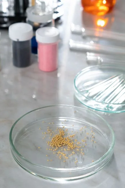
Phenol uptake depends on the wastewater, carbon structure and operating conditions, so a generic surface-area figure cannot define the duty. The EPA fact sheet identifies suspended solids, BOD5, phenol, dissolved oxygen and other organics as constituents that may adversely affect carbon adsorption. It also states that pH and temperature may alter solubility and therefore the adsorption properties of wastewater components onto carbon.
Activated carbon is a porous adsorbent. Its pore structure and surface area affect the number and accessibility of adsorption sites, but these properties alone do not guarantee equivalent phenol capacity. Competing organics can occupy sites, suspended solids can restrict transport through the bed, and the distribution of phenol between water and carbon can change with pH and temperature. The EPA guidance therefore links successful application to both the quality and quantity of wastewater delivered to the adsorption system.
The carbon characterization reported in the Molecules study illustrates the type of information a technical specification should contain. Its tested GAC had a specific surface area of 1059.011 m2/g, total pore volume of 0.625 cm3/g and micropore volume of 0.488 cm3/g (Molecules, 2022). These are properties of the tested material, not universal procurement values for phenol service. That study also examined antibiotics rather than phenol, so its performance data should not be presented as phenol-capacity evidence.
For procurement, require capacity or breakthrough evidence from a comparable water matrix. The supplier should state the analytical method, initial phenol concentration, competing constituents, pH, temperature, flow basis, contact time and endpoint. If representative testing is unavailable, treat the installation as requiring pilot validation rather than extrapolating from generic carbon data.
Size the Carbon Contactor from Project Data
A defensible carbon-contactor size starts with hydraulic flow and a verified contact-time duty. Required inputs are average and peak flow, phenol concentration and variability, required effluent phenol concentration, suspended-solids loading, carbon type, and the operating mode. The EPA reports typical carbon contact time of 15–35 minutes, depending on the application, wastewater constituents and desired effluent quality; this is preliminary guidance, not a universal bed specification.
| Sizing input | How to use it | Evidence or validation required |
|---|---|---|
| Average and peak flow | Establish hydraulic loading and the contactors required while one is offline | Verified flow series and operating envelope |
| Phenol loading and effluent target | Define the adsorption duty | Representative wastewater data and capacity or breakthrough testing |
| Contact time | Select preliminary bed volume | EPA preliminary range: 15–35 minutes, EPA Wastewater Technology Fact Sheet, September 2000 |
| Bed mass | Calculate from selected empty-bed contact time and verified flow | Supplier capacity data and pilot confirmation; no universal phenol mass-loading value is established by the supplied research |
| Hydraulic configuration | Select downflow fixed-bed or upflow expanded-bed operation | Solids loading, backwash method, site constraints and control requirements |
For a preliminary calculation, the selected empty-bed contact time provides the basis for dividing the required bed volume by the selected carbon bulk density, with the mass then checked against the supplier’s phenol-loading evidence and pilot results. The supplied research does not establish a universal phenol mass-loading value, so a final bed mass cannot be responsibly stated without the target-water test data.
The EPA also states that enough contactors should be provided to maintain effective carbon contact time and effluent quality while one column is offline for spent-carbon removal or maintenance. Confirm that the remaining units can meet both obligations during an outage.
Pilot work should verify loading rate, pressure drop, phenol breakthrough and replacement interval with representative wastewater. Add post-filtration where carbon fines could affect effluent turbidity or downstream equipment. The EPA’s Niagara Falls example included oxidation and disinfection after physical-chemical treatment, while the Robbins Reclamation Facility used post-filtration after GAC to meet its 0.5 NTU turbidity permit requirement; those project-specific arrangements illustrate why the receiving requirement belongs in the sizing basis, but they are not universal phenol-system specifications.
Operate, Monitor and Maintain the Filter
Operation should protect the bed from fouling and identify carbon breakthrough before the phenol target is missed. The EPA fact sheet states that influent suspended solids above 20 mg/L require more frequent backwashing to prevent clogging of the carbon bed. Backwash frequency must therefore be tied to solids loading and observed bed behavior rather than a fixed calendar interval alone.
| Monitoring item | Operational purpose | Action trigger |
|---|---|---|
| Inlet and outlet phenol | Measure adsorption performance and establish breakthrough | Increase monitoring frequency or evaluate media condition as the outlet approaches the target |
| Suspended solids | Identify increased bed-fouling risk | Evaluate solids control and more frequent backwashing when inlet concentrations exceed 20 mg/L, as stated by the EPA, September 2000 |
| Differential pressure and flow | Detect restriction, plugging or distribution problems | Inspect the bed, underdrains, distributors and valves |
| pH and temperature | Track variables that can affect solubility and adsorption | Review the duty when operating conditions move outside the qualified envelope |
| Backwash records | Establish actual media-loading and maintenance demand | Revise the backwash program when solids or pressure-drop trends increase |
| Effluent turbidity | Detect carbon fines or solids carryover | Inspect post-filtration and media integrity where required |
Inspect underdrains, distributors and valves for uneven flow and short-circuiting, which can produce premature phenol breakthrough even when the calculated bed mass appears adequate. When one column is offline, verify that the remaining contactors maintain both required contact time and effluent quality.
Set media replacement or regeneration triggers from influent variability, breakthrough data, pressure-drop behavior and treatment performance. A calendar interval can support planning, but it should not replace measured evidence.
For photocatalytic hybrids, the 2026 Scientific Reports study optimized its system at 8 L/min flow, moderate pH, 120 minutes of irradiation, 0.86 g L−1 catalyst, 45 mM H2O2 and an initial phenol concentration of 10 ppm. These are laboratory reactor conditions, not standard procurement specifications for a GAC contactor.
Compare Carbon Treatment Routes
The correct carbon-treatment route follows from the wastewater condition and the required phenol reduction. GAC-only polishing is appropriate only when load, competing organics and solids are sufficiently controlled and the plant can maintain the defined contact-time duty. It is not a substitute for biological or oxidation control where those upstream loads would overload the bed.
| Treatment route | Best fit | Principal limitation |
|---|---|---|
| GAC-only polishing | Controlled industrial effluent requiring a defined dissolved-phenol reduction | Limited tolerance for variable phenol, competing organics and solids; breakthrough requires media replacement or regeneration. |
| GAC with upstream solids or biological control | Wastewater with manageable biodegradable load but suspended solids or BOD5 that could impair adsorption | More equipment, controls and operating interfaces; the upstream process must be stable at the carbon inlet. |
| GAC coupled with oxidation | Treatment-train evaluation where oxidation can reduce part of the organic load before adsorption | Combination performance is matrix-specific; the Indonesian Journal of Chemistry result was developed on tofu-industry wastewater. |
| Standalone advanced oxidation | Projects evaluating photocatalytic or chemical oxidation as the primary phenol-removal route | The 2026 Scientific Reports evidence is laboratory-based and uses a modified carbon-supported catalyst system rather than a conventional full-scale GAC column. |
For GAC with pretreatment, the decision follows directly from the EPA warning that suspended solids, BOD5, phenol and dissolved oxygen can adversely affect adsorption. For oxidation-assisted GAC, the Indonesian Journal of Chemistry study supports the principle of combining ozonation with adsorption, while the 2026 Scientific Reports study shows why process-specific optimization is necessary. Neither result should be presented as direct proof of full-scale GAC-column performance.
When comparing DAF with clarification before the carbon stage, use the comparison of DAF and clarifier pretreatment for chemical wastewater to structure the question. Where a downstream biological stage remains under consideration, compare MBR and conventional activated sludge for chemical wastewater before fixing the treatment train.
Plan Media Supply, Regeneration and Total Cost
Media management is a separate procurement decision from the contactor vessel. On-site regeneration, off-site regeneration and spent-media replacement have different logistics, operating responsibilities and cost structures. The selected route should be stated explicitly before comparing supplier proposals.
The EPA fact sheet says construction and operation and maintenance costs depend on wastewater characteristics, plant capacity and site conditions; it also identifies flow rate, bed depth, operating capacity and regeneration arrangement as inputs to comparative cost estimates. Its listed construction elements include carbon contactors, carbon transport systems, storage tanks, regeneration equipment where applicable, influent pumps where needed and the backwash system.
Budget scope should therefore include:
- Carbon media, vessels, underdrains, valves, instrumentation and required pumping.
- Backwash equipment, water or air demand, controls and post-filtration.
- Media loading, testing and startup support.
- Carbon transport and storage.
- Regeneration, disposal or replacement logistics.
- Downstream solids removal where carbon fines or backwash solids require it.
Ask each supplier to state what its price includes. Do not compare vessel-only quotations with proposals that include media, initial testing, startup, backwash controls, instrumentation or media replacement. Request a lifecycle proposal stating the replacement assumptions, expected backwash frequency, changeout logistics and performance basis.
Any performance guarantee should be tied to a defined influent envelope and effluent target. If the supplier cannot test the actual wastewater matrix, identify that limitation in the acceptance plan. Coordinate carbon media and wastewater filter components as one complete operating system rather than treating media as an interchangeable consumable.
Questions to Ask Before Ordering a Phenol Filter
A supplier should demonstrate the sizing basis, not simply provide a vessel and a generic carbon designation. Before ordering an activated carbon filter for phenol wastewater, require the following:
- Design basis: Identify average and peak flow, selected contact time, proposed bed mass, carbon type, hydraulic loading rate, pressure-drop allowance and expected effluent basis.
- Capacity evidence: Provide phenol capacity or breakthrough results in a comparable water matrix, including the analytical method and test conditions.
- Wastewater envelope: Explain how variations in suspended solids, BOD5, dissolved oxygen, pH and temperature affect the proposed duty and qualified operating range.
- Controls and maintenance: Specify backwash frequency and controls, differential-pressure instrumentation, carbon-fine management and the changeout or regeneration procedure.
- Acceptance: Define the acceptance test, media warranty, spare-parts strategy, startup responsibilities and accountability for each system component.
Also require a written treatment objective. “Phenol removal” should be expressed as a measurable inlet condition, outlet target, hydraulic condition and test method. If the supplier relies on generic surface area, adsorption capacity or laboratory oxidation results, ask how those data apply to the proposed contactor and actual wastewater.
For pretreatment, request an integrated process description showing where solids, biodegradable organics, oxidation demand and carbon breakthrough are controlled. This prevents a common procurement error: selecting a carbon bed first and forcing upstream and downstream duties onto it afterward.
Frequently Asked Questions
Does activated carbon remove phenol from industrial wastewater?
Yes. GAC adsorbs dissolved phenol, but the degree of removal depends on carbon type, contact time, pH, temperature, competing organics, suspended solids and the treatment objective. The EPA describes GAC as advanced tertiary treatment or one component of a physical-chemical train; it does not establish that a standalone carbon filter will meet every phenol limit.
What size activated carbon filter does a phenol wastewater system need?
Size it from verified flow, phenol loading, effluent target, suspended-solids loading and representative breakthrough data. The EPA gives 15–35 minutes as typical carbon contact time, depending on the application, wastewater constituents and desired effluent quality, but this is preliminary guidance rather than a universal bed specification. Request the calculated bed mass, hydraulic loading, pressure-drop basis and pilot results.
Is GAC alone enough for high-phenol wastewater?
It may not be. Direct GAC treatment is more credible where phenol and competing-organics loads are controlled, solids are managed and the required contact-time duty can be maintained. High or variable loads, bed fouling, competition for adsorption sites or a downstream biological oxygen demand can justify biological, physical or oxidation pretreatment.
How much does an activated carbon phenol treatment system cost?
No supported single price is available from the research. The EPA states that costs depend on wastewater characteristics, plant capacity, site conditions, flow rate, bed depth, operating capacity and the regeneration arrangement. Request a lifecycle quotation that separately identifies vessels, media, pumping, backwash, instrumentation, post-filtration, testing, startup, regeneration or replacement, and carbon transport and disposal.
How do I select a phenol wastewater filter supplier?
Require a target-water capacity test, sizing calculations, carbon and vessel specifications, instrumentation, backwash and changeout procedures, acceptance criteria and a transparent regeneration or replacement plan. Confirm that any guarantee is tied to a defined influent envelope and effluent target. Treat a supplier unable to explain how suspended solids, BOD5, dissolved oxygen, pH and temperature affect the proposed duty as a compliance and operating risk.