Which Data Center Wastewater Streams Need Separate Treatment?
A data center in Subang Jaya needs separate treatment trains for sanitary sewage, cooling-tower blowdown, RO reject, softener waste and temporary maintenance or construction discharges. Cooling blowdown should be characterized for flow, temperature, pH, conductivity or TDS, hardness, silica, alkalinity, iron and residual chemicals, then treated for verified cooling make-up reuse or an authority-approved discharge route. Reuse commonly requires membrane pretreatment and RO, while sanitary sewage requires biological treatment and disinfection. Final equipment sizing depends on measured or design flows, feed chemistry and written discharge conditions—not generic examples such as IDE's industry figure of up to 2 million liters per day for a 100-megawatt facility.
Cooling-tower blowdown is the water deliberately removed from a recirculating cooling system to control dissolved-material buildup caused by evaporation. It is replaced by fresh make-up water and is not the same stream as sanitary sewage, RO reject, softener brine or temporary closed-loop fill-and-flush discharge. HydropureWater’s 2026 regional planning guidance states that combining these streams can conceal incompatible chemistry, obscure the water balance and produce a discharge that does not match the receiving utility’s requirements.
Sanitary sewage contains organic matter, nutrients and pathogens, so it should be directed to biological treatment and disinfection. Cooling blowdown instead contains concentrated dissolved minerals, heat, residual biocides, and scale or corrosion inhibitors; its treatment must therefore follow its specific destination and chemistry. RO reject, softener brine, maintenance drain-downs and construction flushing require separate assessment before recombination, reuse or discharge.
Use the following stream-by-stream design matrix:
| Stream | Main characteristics | Required assessment | Potential destination |
|---|---|---|---|
| Sanitary sewage | Organic matter, nutrients, pathogens | Hydraulic and organic loading | Sanitary treatment and disinfection |
| Cooling-tower blowdown | Concentrated minerals, heat, biocides and treatment chemicals | Flow, temperature, pH, TDS, hardness, silica, alkalinity, iron and residuals | Cooling make-up reuse or controlled discharge |
| RO reject | Concentrated dissolved salts and treatment residuals | Salt loading, flow, chemistry and disposal route | Further treatment, controlled reuse or permitted disposal |
| Softener waste | Ion-exchange regenerant and dissolved mineral salts | Regenerant chemistry and recovery option | Validated recovery or disposal route |
| Maintenance or construction flushing | Suspended solids, corrosion-control residues, cleaning chemicals or bacteria | Representative sampling and authority review | Approved treatment or off-site disposal |
Ask the mechanical and environmental teams to provide average and peak hourly and daily flows, the cooling configuration, make-up-water source, cycles of concentration, operating temperature, evaporation rate, chemicals added and written discharge conditions. The regional data center wastewater treatment planning guide provides a useful structure for collecting this information before selecting equipment.
What Must Site Testing Establish Before Equipment Is Sized?
Site-specific flow and chemistry data determine hydraulic capacity, pretreatment requirements and whether blowdown can meet a cooling make-up specification. Representative testing should therefore precede equipment sizing, not merely validate a package selected from a catalogue.
Begin by separating measurements by stream. For cooling blowdown, test temperature, pH, conductivity or TDS, silica, calcium, magnesium, hardness, alkalinity, iron and residual treatment chemicals. The analysis should also identify suspended solids and colloids where reuse is being considered. For sanitary sewage, establish the hydraulic profile and organic and nutrient loading. For RO reject and softener waste, characterize the regenerant or treatment chemicals, dissolved salts and expected variability.
Record average and peak hourly and daily flows by stream. These values set treatment capacity, storage, equalization and pumping requirements. Where the facility is still being designed, obtain design flows from the cooling designer and identify which values remain provisional. HydropureWater’s 2026 planning guidance emphasizes that blowdown volume depends on cooling design, climate and make-up-water quality, so the mechanical engineer should provide the flows rather than applying a generic rule of thumb.
Document the cooling configuration, make-up source, cycles of concentration, evaporation rate, chemicals added and operating temperature. These inputs determine the available reuse flow, the expected concentrate generation and the chemistry that the final treatment train must handle. Use site measurements rather than regional assumptions: tropical ambient conditions and make-up chemistry alter the operating profile, but neither establishes the design basis by itself.
Do not size from IDE’s figure of up to 2 million liters per day for a 100-megawatt facility. IDE presents that value as an industry-scale example in its 2026 data-center water-reuse article, not as a sizing rule for a Subang Jaya project. It cannot substitute for stream-level flow and chemistry data.
Also obtain the written discharge conditions before finalizing the process. Sewer capacity, connection conditions, applicable limits and the approval pathway determine whether the proposed treatment train can serve as a discharge solution. This review should use the membrane and filter-element technical information to identify the data required for an appropriate pretreatment and membrane comparison.
How Should the Subang Jaya Treatment Process Flow Be Built?
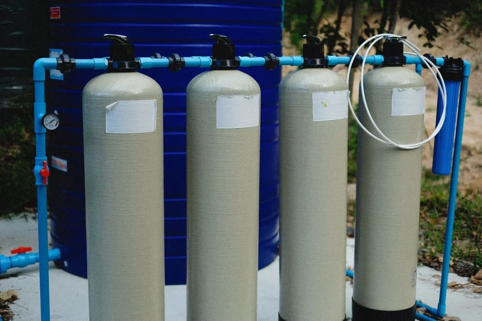
The process flow should follow the required destination of each stream—cooling make-up reuse, sanitary treatment, controlled discharge or temporary disposal—not a preferred equipment category. Each branch needs its own pretreatment, final treatment, monitoring and concentrate or solids destination.
- Establish the destination. Define whether the project seeks cooling make-up reuse, sanitary treatment, controlled discharge or temporary disposal.
- Characterize the feed. Use measured or design flows and site chemistry for each branch.
- Remove contaminants that protect downstream processes. Apply filtration, softening, biological treatment or other pretreatment according to the receiving process.
- Select final treatment. Use membrane treatment for validated water reuse, disinfection for sanitary sewage and flow-controlled monitoring for permitted discharge.
- Close the balance. Identify where permeate, concentrate, sludge and solids leave the site.
For cooling make-up reuse, remove suspended solids and colloids before addressing hardness, scaling species and residual treatment chemicals. Evaluate ultrafiltration pretreatment for cooling blowdown as a possible barrier stage, not as a dissolved-salt-removal process. HydropureWater specifies its UF systems at 2,000–40,000 L/h, with 0.03-micron PVDF membranes, turbidity up to 300 ppm, automatic backwash and air scour. Confirm that the actual blowdown condition falls within that envelope.
An industrial RO system for cooling make-up reuse may then provide the permeate-producing stage. Validate the product chemistry, temperature, corrosion compatibility and blending against the cooling-system specification. The required scaling controls depend on silica, calcium carbonate, calcium sulfate and the residual treatment programme; a laboratory result alone does not establish long-term operating compatibility.
Route sanitary sewage through biological treatment and disinfection. HydropureWater’s 2026 source describes the underground WSZ package sewage treatment plant as providing A/O treatment, sedimentation and disinfection at 1–80 m³/h, while the integrated MBR wastewater treatment system covers 10–2,000 m³/day and provides filtration below 1 μm. These are catalogue envelopes, not automatic selections; sanitary loading and site constraints must still be checked.
For controlled discharge, characterize the stream, apply pretreatment where required, control flow and monitor compliance. Written authority acceptance is required before treating the route as viable. Construction fill-and-flush water requires separate characterization and an authority-approved treatment or off-site disposal route.
| Destination | Pretreatment | Final treatment | Monitoring and unresolved item |
|---|---|---|---|
| Cooling make-up reuse | Filtration and chemistry-specific control | UF followed by RO and controlled blending | pH, conductivity, solids, scaling species, residual chemicals and concentrate route |
| Sanitary treatment | Screening and equalization | Biological treatment, clarification and disinfection | Organic loading, nutrients, pathogens and sewer acceptance |
| Controlled discharge | Stream-specific removal of suspended solids, metals, heat or treatment residuals | Treatment and flow-control train | Applicable discharge limits, sampling point and authority approval |
| Construction flushing | Characterization and containment | Treatment or off-site disposal | Disposal authorization and acceptance of the tested discharge |
When Is Blowdown-to-Make-Up Reuse Economically and Technically Feasible?
Blowdown reuse is feasible only when the recovered water satisfies the cooling system’s chemistry and operating requirements and the residual concentrate has a defined destination. The decision is therefore a water-balance and mass-balance problem, not simply a choice between RO and discharge.
The balance should include evaporation, blowdown, fresh make-up, treated permeate, RO reject, precipitation solids, softener waste and any change in cooling cycles of concentration. A flow diagram must show where every concentrate and solid stream leaves the system and who accepts it. If the balance does not close, reuse merely relocates the wastewater problem.
Use conductivity, pH and suspended solids as baseline operating variables, with laboratory confirmation of silica, hardness, alkalinity, iron, temperature and residual chemicals for the design basis. The treated-water chemistry and any residual treatment chemicals must then be checked against the cooling-system specification. Data center blowdown treatment in another water-constrained location illustrates why site chemistry remains central to process selection.
IDE reports in 2026 that conventional brackish-water reverse osmosis is commonly limited to 75–80% recovery because silica, calcium carbonate and calcium sulfate constrain scaling. Higher recovery requires a process-specific design and concentrate plan. IDE also describes an industrial application at around 95% recovery with permeate silica of about 1 mg/L, using controlled salt precipitation and membrane treatment. That is evidence that advanced configurations exist, not a guaranteed result for Subang Jaya.
Controlled salt precipitation can convert sparingly soluble salts into a manageable solid stream. The route then requires chemical management, solids withdrawal and a defined disposal destination. A buyer should not accept “high recovery” without the salt balance, precipitation design, residual handling and disposal basis.
The cycles-of-concentration calculation also needs precision. Genesis Water Technologies’ comparison states that at 4 cycles of concentration the theoretical blowdown ratio is 25% of make-up volume, while at 6 cycles it is 20%. Moving between those points is a 20% relative reduction in blowdown, not a 50% improvement. The resulting increase in cycles must also remain compatible with scaling, corrosion and biological control.
Where reuse cannot be demonstrated safely or economically, specify a permitted discharge treatment train instead of treating uncontrolled dilution as treatment. Authority acceptance, pretreatment, flow control and compliance monitoring then become essential parts of the design.
Which Malaysian Discharge Requirements Must the Design Address?
The design should address the Environmental Quality (Industrial Effluent) Regulations 2009, P.U.(A) 434, while confirming the applicable category, receiving route and current site conditions with the relevant authority. The supplied regulatory discussion distinguishes Standard A for inland-water discharge from Standard B for sewer discharge.
The supplied parameter set is pH 5.5–9.0; total suspended solids no more than 100 mg/L under Standard A and 50 mg/L under Standard B; residual chlorine no more than 1 mg/L; and temperature no more than 40°C. Where relevant, the supplied discussion gives zinc limits of 1.0 mg/L under Standard A and 2.0 mg/L under Standard B, copper limits of 0.2 and 1.0 mg/L, and chromium limits of 0.05 and 0.5 mg/L.
These values are regulatory context for design review, not a substitute for a site-specific approval. Confirm the receiving-water options, sewer capacity, connection conditions, applicable limits, pretreatment requirements and approval pathway in writing before finalizing an equipment guarantee. The Malaysia sewage treatment and compliance considerations provide a useful authority-facing checklist.
| Parameter | Standard A: inland-water discharge | Standard B: sewer discharge | Procurement action |
|---|---|---|---|
| pH | 5.5–9.0 | 5.5–9.0 | Confirm the applicable range and required monitoring point |
| TSS | No more than 100 mg/L | No more than 50 mg/L | Define solids removal and sampling requirements |
| Residual chlorine | No more than 1 mg/L | No more than 1 mg/L | Set dechlorination or residual-control provisions |
| Temperature | No more than 40°C | No more than 40°C | Include cooling and equalization requirements |
| Zinc | 1.0 mg/L | 2.0 mg/L | Review cooling-chemical inputs and pretreatment |
| Copper | 0.2 mg/L | 1.0 mg/L | Confirm whether the selected route is affected |
| Chromium | 0.05 mg/L | 0.5 mg/L | Confirm whether the selected route is affected |
Do not assume that sewer headroom at the receiving plant eliminates connection, lift-station or extension constraints. The authority should confirm the complete discharge pathway, including any infrastructure contribution, before the commercial route is fixed.
What Should a Supplier Guarantee Before Equipment Procurement?
A supplier should guarantee a site-specific process result rather than a generic package envelope. The technical basis must connect the measured or design feed to the agreed destination, applicable authority conditions and a defined concentrate route.
Require a process flow diagram, hydraulic profile, equipment list, controls narrative, utility demand and site-specific performance basis. For membrane systems, request the recovery calculation, scaling and fouling assessment, cleaning strategy, redundancy arrangement and concentrate-management assumptions. Automatic dosing should be assessed within the controls narrative, including compatibility with the proposed feed chemistry; an automatic chemical dosing system is not a substitute for that design work.
The guarantee should state the design-flow range, product-water quality, recovery, chemical consumption and accepted route for concentrate or solids. It should also identify standby arrangements, fail-safe controls, cleaning access and any effect on cooling availability. Any guarantee of recovery or water quality must refer to the proposed feed composition and site conditions, not only the manufacturer’s standard product envelope.
Price the full lifecycle, not just the purchase price: membrane replacement, energy, chemicals, operator attention, solids handling, standby equipment, downtime and any sewer-extension obligation. The commercial schedule should also state exclusions, assumed flows and chemistry, treatment objectives, discharge assumptions, testing obligations and items requiring local authority confirmation.
Include commissioning, laboratory testing, operator training, documentation, local service capability, critical spares and contractual acceptance criteria in the supply scope. The delivery programme should account for authority approvals, site preparation, long-lead equipment and wet commissioning. If the supplier cannot demonstrate how the equipment handles the proposed feed chemistry or where its concentrate goes, the performance guarantee is incomplete.
Frequently Asked Questions
How much should a Subang Jaya data center budget for wastewater and cooling blowdown treatment?
No responsible project price can be stated without measured or design flows, feed chemistry, reuse objectives, authority conditions, pretreatment requirements and concentrate handling. Request a feasibility quotation that states its exclusions and assumptions, then price capital and lifecycle costs separately. A site-specific treatment procurement guide provides useful checking points, but it is not a Malaysian price basis.
Should a data center use UF, RO or MBR for cooling blowdown?
UF addresses particulates and colloids before RO but does not remove dissolved salts. RO can produce low-salt permeate for a validated cooling make-up application, while MBR is directed at biological sewage treatment and does not solve concentrate disposal. Select the train from the intended destination and measured feed chemistry.
What recovery can a cooling-tower blowdown RO system guarantee?
IDE reports 75–80% for conventional brackish-water RO and around 95% for a particular industrial high-recovery application in 2026. The Subang Jaya guarantee must follow site chemistry and a validated scaling assessment; neither figure can be transferred to an untested feed.
Can cooling blowdown and sanitary sewage be discharged to the same sewer?
Keep the streams separate until the authority confirms the route and a validated water and mass balance demonstrates compatibility. Obtain written confirmation of sewer capacity, connection conditions, applicable limits and pretreatment requirements before combining them in the performance basis.