Why Aurangabad Is a Strategic — but Water-Sensitive — Data Center Site in 2026
Aurangabad sits inside the Marathwada region, which the Government of Maharashtra and central water agencies routinely classify as a water-stressed zone, so new data center proposals now have to demonstrate a water-positive design intent to clear the India Data Centre Policy 2020 screening layer. The proximity of the MIDC Waluj and MIDC Chikalthana industrial belts means the data center will be treated as an industrial discharger from day one, with discharge rules that overlap with MPCB Consent to Establish (CTE) and Consent to Operate (CTO) conditions applied to existing units in the same cluster.
A single 100 MW facility can demand up to 2 million liters of water per day (IDE Tech, 2026), so even one hyperscale block begins to rival the daily draw of a small Aurangabad town once evaporative cooling, humidification and chiller makeup are aggregated. Global data centers are overwhelmingly water-cooled — about 75–90% use water-based cooling and roughly 57% draw from potable supplies (UGA field report, 2026) — which means an Aurangabad campus pulling from the Jalna–Paithan supply reservoirs will be in direct competition with municipal and agricultural users during dry-season allocation cycles. The strategic case for a reuse-led design is therefore not optional: it is the cheapest way to keep freshwater draw within the consent envelope that the state is increasingly willing to enforce.
Water Chemistry of Cooling Tower Blowdown in Aurangabad Conditions
Cooling tower blowdown concentrates everything that is not evaporated, so its total dissolved solids (TDS) typically sit 4–8 times above the makeup TDS and, at 4 cycles of concentration, routinely land in the 1,200–6,000 mg/L range for hard Marathwada groundwater (Genesis Water Tech, 2026). The scaling minerals of concern — calcium, magnesium, silica and alkalinity — accumulate with cycles of concentration, and silica is frequently the limiting ion for high-recovery RO in Maharashtra groundwaters because it does not respond to standard antiscalant chemistry alone. Treatment chemicals used in the cooling loop (biocides, corrosion inhibitors, scale inhibitors and dispersants) all end up in the blowdown, and any legacy phosphate or chromate chemistry will foul downstream RO membranes; the engineer should request the current chemical inventory from the client before finalizing the recovery train. Suspended solids from corrosion products, biofilm fragments and airborne dust typically measure 10–50 mg/L in the blowdown, and biological loading is non-trivial because evaporative cooling operates at warm temperatures year-round in Aurangabad and biofilm sloughing events are common. The table below sets the input band an Aurangabad design should be benchmarked against.
| Parameter | Typical Marathwada Makeup | Cooling Tower Blowdown (≈4 cycles) | Design Implication |
|---|---|---|---|
| Total dissolved solids | 300–800 mg/L | 1,200–6,000 mg/L | Sets RO feed osmotic pressure and concentrate routing |
| Calcium hardness (as CaCO₃) | 150–350 mg/L | 600–2,800 mg/L | Drives antiscalant selection and CaSO₄ scaling risk |
| Silica (SiO₂) | 15–40 mg/L | 60–320 mg/L | Limits RO recovery to ~75–80% without precipitation control |
| Alkalinity (as CaCO₃) | 100–250 mg/L | 400–2,000 mg/L | Controls CO₂ release and CaCO₃ scaling tendency |
| Suspended solids | 5–20 mg/L | 10–50 mg/L | Defines pretreatment filter loading |
| Residual chlorine / biocides | 0.2–0.5 mg/L (system) | Variable, often higher in slug doses | Must be neutralized before RO membranes |
Blowdown Treatment Train: From Pretreatment to RO Permeate
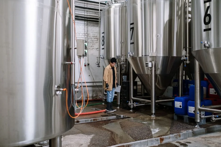
The unit operations an Aurangabad engineer will specify on the P&ID follow a fixed sequence: side-stream filtration to drop suspended solids, ultrafiltration as a membrane barrier, antiscalant-conditioned brackish-water RO to produce reuse permeate, and an evaporative polishing step if the recovery target exceeds 80%. A self-cleaning spiral side-stream filter sized at 1–5% of circulation flow reduces suspended solids to levels that protect downstream UF/RO membranes without backwash downtime (Genesis Water Tech, 2026). Downstream of that, a PVDF ultrafiltration stage with 0.01–0.1 micron membranes runs at 10–30 psi, achieves 90–95% recovery and acts as an absolute barrier against bacteria, viruses and colloids that would otherwise foul the RO. An PVDF ultrafiltration pretreatment ahead of RO is the most reliable way to hold silt density index (SDI) below the 3 limit that brackish RO elements require. The antiscalant-conditioned BWRO unit then delivers permeate in the 10–50 mg/L TDS range, removes 95–99% of dissolved solids and is sized for 50–75% local recovery before concentrate routing (Genesis Water Tech, 2026); the engineer should select an industrial RO system for blowdown reuse with a documented scaling projection against the Aurangabad silica band. Beyond ~80% local recovery, conventional BWRO fails because silica, calcium carbonate and calcium sulfate reach saturation; high-recovery designs use controlled precipitation of those salts and then loop the residual NaCl-rich brine to push overall recovery toward 95% (IDE Tech, 2026). For partial ZLD, a mechanical vapor compression (MVC) brine concentrator processes the RO concentrate to 95–98% recovery, producing distillate below 10 mg/L TDS and a 20–30% solids brine stream that is small enough to handle with a crystallizer or evaporation pond (Genesis Water Tech, 2026). The table below summarizes the unit-operation envelope an Aurangabad P&ID should be built around.
| Stage | Typical Recovery | Output Quality | Key Operating Range |
|---|---|---|---|
| Self-cleaning spiral side-stream filter | Continuous (1–5% of circulation) | 10–25 micron removal | No backwash; mechanical purge |
| Multi-media filter (SDI control) | Continuous | Feed SDI < 5 | Sand + anthracite + garnet |
| PVDF ultrafiltration | 90–95% | SDI < 3, turbidity < 0.2 NTU | 10–30 psi; CIP every 1–3 months |
| Antiscalant + BWRO | 50–75% local; up to 80% with high-recovery design | Permeate 10–50 mg/L TDS | 150–400 psi feed pressure |
| MVC / brine concentrator (partial ZLD) | 95–98% on concentrate | Distillate < 10 mg/L TDS | 15–25 kWh per 1,000 US gal distillate |
MPCB Consent, CPCB Limits and the Zero-Liquid-Discharge Question
The regulatory stack that governs an Aurangabad data center has three layers, and the design must clear all three before the first liter of blowdown leaves the boundary. The CPCB schedule for cooling tower blowdown sets effluent limits on pH, total suspended solids, total dissolved solids, oil and grease, residual chlorine and residual copper, and the values must be checked against the latest CPCB schedule rather than carried over from older project templates. MPCB issues Consent to Establish (CTE) before construction and Consent to Operate (CTO) before commissioning, both under the Water Act and Air Act, and new data centers in notified industrial areas are increasingly being asked to commit to zero liquid discharge as a consent condition (Genesis Water Tech, 2026). Discharge to the Aurangabad Municipal Corporation sewer requires trade-effluent negotiations and usually caps TDS; the engineer should obtain the local ULB sewer acceptance limits in writing before finalizing concentrate handling. If the site is within 1 km of a notified river stretch or a CRZ area, additional clearances from the state environment impact assessment authority can extend the consent timeline by 6–12 months. The table below maps each consent layer to its design consequence.
| Consent Layer | Issuing Authority | Trigger | Design Consequence |
|---|---|---|---|
| CTE (Consent to Establish) | MPCB | Before construction | Freezes site boundary, effluent quantity and quality |
| CTO (Consent to Operate) | MPCB | Before commissioning | Operating limits on TDS, pH, residual chlorine, copper |
| Trade-effluent discharge | Aurangabad Municipal Corporation | Sewer connection | Local TDS cap; consent must be filed before any discharge |
| CRZ / river-setback clearance | State EIAA / MoEFCC | Site within 1 km of notified water body | Adds 6–12 months to consent timeline |
| ZLD commitment | MPCB (increasingly) | Industrial-area classification | Brine concentrator + crystallizer or evaporation pond |
Reuse, Partial ZLD or Full ZLD: A 2026 Decision Framework for Aurangabad
The choice between reuse, partial ZLD and full ZLD is fundamentally an economic decision, with the MPCB consent document acting as the constraint. Cooling tower makeup reuse at 60–85% recovery is the highest-value first step because it cuts freshwater cost and discharge fees simultaneously (Genesis Water Tech, 2026) and is the default in any design where MPCB has not imposed zero discharge. Partial ZLD — RO plus brine concentrator — reduces liquid discharge by 80–90% and captures most of the water benefit at substantially lower capex than a full crystallizer train, and is the practical default for Aurangabad unless the consent document explicitly mandates full ZLD (Genesis Water Tech, 2026). Full ZLD — RO plus MVC plus crystallizer — delivers 95–99% overall water recovery, but is only justified when discharge is genuinely prohibited or when freshwater cost is high enough to amortize the crystallizer; published ZLD systems run $3–8 million in capex and $5–15 per thousand gallons in opex (Genesis Water Tech, 2026). Discharge fees in water-stressed regions already exceed $5–15 per thousand gallons (Genesis Water Tech, 2026), which in Maharashtra translates to a meaningful per-kL avoided cost that should be passed to the client as part of the ROI. A PLC-controlled antiscalant and biocide dosing skid and a multi-media filter for SDI control are the lowest-cost additions that move a reuse-only design toward a partial-ZLD envelope without committing to a crystallizer. The decision table below is the version the engineer should put in front of the steering committee.
| Strategy | Overall Water Recovery | Indicative Capex Band | Triggering Condition in Aurangabad |
|---|---|---|---|
| Cooling tower makeup reuse only (RO) | 60–85% | Lowest (RO skids only) | MPCB allows discharge to ULB sewer with TDS cap |
| Partial ZLD (RO + MVC brine concentrator) | 85–95% | Mid (MVC adds $1–3 M) | Industrial-area site with tightening discharge rules |
| Full ZLD (RO + MVC + crystallizer) | 95–99% | Highest ($3–8 M) | MPCB consent explicitly mandates zero liquid discharge |
Capital and Operating Cost Bands for an Aurangabad Data Center Water Plant
The capex envelope for an Aurangabad water plant is dominated by the RO skid, the brine concentrator (if partial ZLD is selected) and the crystallizer (if full ZLD is selected). Published industrial RO systems for blowdown duty in the 50,000 GPD range are quoted in the $250,000–500,000 band; in India the project cost varies with import content versus local fabrication, so the final figure should be obtained from current vendor quotes rather than carried over from US reference projects (Genesis Water Tech, 2026). RO operating cost sits in the $1.50–3.00 per thousand gallons range, dominated by energy, antiscalant chemicals and membrane replacement (Genesis Water Tech, 2026). A mechanical vapor compression brine concentrator adds $1–3 million of capex and 15–25 kWh per 1,000 gallons of distillate, so its viability depends on the Aurangabad electricity tariff structure and any captive solar PPA (Genesis Water Tech, 2026). Full ZLD systems range from $3–8 million and are typically evaluated only when the consent document explicitly requires zero liquid discharge (Genesis Water Tech, 2026); the engineer should treat these as upper-bound reference figures, not as quoted prices for an Indian build.
Frequently Asked Questions
What size RO skid do we need for a 100 MW data center in Aurangabad?
Size the blowdown RO around the cooling-tower cycles of concentration and the daily blowdown volume, not the IT load. For a facility drawing up to 2 million liters per day (IDE Tech, 2026) and operating at 4 cycles of concentration, blowdown typically falls in the hundreds of thousands of liters per day, which maps to a 50,000 GPD-class RO skid in the $250,000–500,000 published band (Genesis Water Tech, 2026). The engineer should request the final blowdown flow and the silica number from the cooling-tower vendor before locking the skid size, because silica is the limiting ion in Marathwada groundwater.
Will MPCB force us into full ZLD, or can we discharge to the Aurangabad municipal sewer?
It depends on the consent document. New data centers in notified industrial areas are increasingly being asked to commit to zero liquid discharge as a consent condition, but a reuse-plus-discharge design is still negotiable where the Aurangabad Municipal Corporation trade-effluent agreement caps TDS within the CPCB schedule. The engineer should obtain the draft CTE conditions from MPCB and the ULB sewer acceptance limits in writing before finalizing the concentrate handling train, because the answer determines whether a brine concentrator or a crystallizer has to be in the capex envelope.
How do we choose between a greenfield RO plant and a retrofit onto an existing cooling system?
Greenfield builds can be designed around 60–85% recovery from day one and avoid retrofit constraints on footprint, chemical compatibility and discharge routing. Retrofits are usually limited by the existing chemical program — legacy phosphate or chromate chemistry will foul RO membranes — and by the available plot area for side-stream filtration and a brine concentrator. The engineer should request the current cooling-water chemical inventory and the available plot dimensions before recommending a retrofit, because those two inputs decide whether the project is feasible at all.
What is the realistic timeline from pilot to commissioning for an Aurangabad data center water plant?
Pilot testing typically runs 8–16 weeks once the feed water and chemical inventory are confirmed, and MPCB consent processing is the gating item rather than the engineering. CTE and CTO applications run in parallel with detailed design, and sites within 1 km of a notified river stretch or a CRZ area should add 6–12 months for the state EIAA clearance. A realistic greenfield schedule from pilot start to commissioning is therefore 12–18 months for a reuse-only design and 18–24 months if partial ZLD triggers an MVC procurement and an extended consent review.