
Why Petrochemical Wastewater Needs a DAF Pre-Treatment Step
Petrochemical wastewater carries a pollutant mix that a biological stage cannot tolerate without conditioning: free oil, emulsified oil, suspended solids, dissolved hydrocarbons, and phenols all arrive together in the equalization basin (Water Science & Technology, 2001). The role of dissolved air flotation in the chain is to remove hydrocarbons, suspended solids, and phenols to protect the biological treatment that follows (Water Science & Technology, 2001). A typical petrochemical train runs source → equalization → API or CPI separator → DAF → biological (activated sludge, MBBR or SBR) → tertiary clarification → disinfection or reuse, with DAF positioned to remove floatables and colloidal load before biology.
DAF functions as part of a multi-stage process rather than a standalone solution. The API separator ahead of it is a gravity device that pulls out the bulk free oil, while the DAF unit targets the emulsified oil fraction, fine TSS, and flocculable hydrocarbons that the API separator cannot catch. When the DAF is skipped or undersized, the biological stage experiences emulsified oil breakthrough, fluctuating FOG load, and phenol spikes, leading to unstable treatment. Treat DAF as the conditioning step that makes the rest of the flowsheet operable, not as a polishing unit.
How Dissolved Air Flotation Works on an Oily Stream
Clean water is pressurized in a recirculation loop, mixed with air until the water reaches saturation, then released into the flotation cell where the pressure drop nucleates micro-bubbles (Clearwater Industries). These micro-bubbles attach to oil droplets and flocculated solids, carrying them to the surface where a skimmer sweeps the floating sludge into a trough while clarified water is withdrawn from below (Clearwater Industries). Following this mechanical separation, the system ensures the effluent meets the specific requirements of the downstream biological stage.
Commercial DAF units produce micro-bubbles in the 30–50 micron range—small enough to attach to fine oil droplets and colloidal floc, yet large enough to retain buoyant lift in the cell (Clearwater Industries). Bubble–particle attachment is the rate-controlling step, which is why chemical conditioning ahead of the cell matters as much as the mechanical bubble generator.
For a refinery or petrochemical complex, the practical consequence is unit sizing. The HydropureWater DAF system is built across 13 standard models covering 4–300 m³/h, spanning both small specialty chemical plants and large integrated complexes without forcing a custom build for every flow rate (HydropureWater product catalog).
What DAF Actually Removes from Petrochemical Wastewater
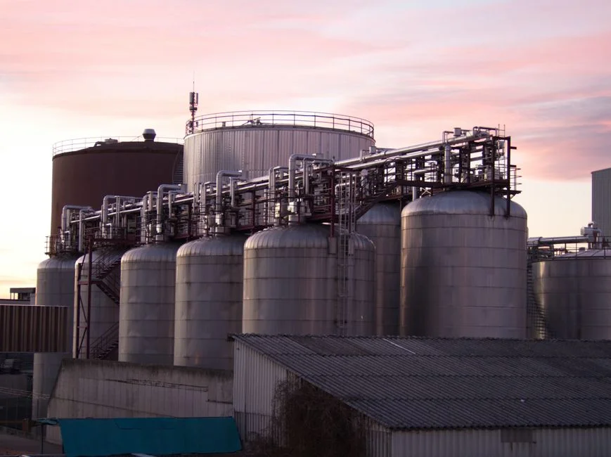
Free and dispersed oil is the primary target: micro-bubbles attach to droplets and lift them, often without chemical aid when the influent oil is already in a coarse dispersion. Emulsified oil requires destabilization through coagulant and flocculant addition so that the droplets grow and become floatable. Without that conditioning step, emulsified oil passes through the cell largely untouched.
Suspended solids are removed effectively when the air-to-solids ratio is sized to the influent solids load and the chemistry is correct; the Water Science & Technology study (2001) used jar-test-style batch experiments to map suspended-solids removal as a function of flocculant type and air-to-solids ratio. Hydrocarbons and phenols follow the same control variables, with the same study reporting measurable removal of both parameters as flocculant dose and A/S ratio were varied.
DAF does not remove dissolved salts, true dissolved BOD, ammonia, or refractory organics, as those are handled by the biological and tertiary steps downstream. The DAF effluent is a conditioned feed to biology, not a discharge-quality stream. The downstream biological stage must be sized for the residual load after DAF, with shock-loading margin for upset cases.
Design Parameters That Decide DAF Performance
Vendor proposals should be evaluated against a defined operating window. The key parameters, with the evidence behind each, are summarized below.
| Parameter | Typical Range / Value | Source |
|---|---|---|
| Micro-bubble size | 30–50 micron | Clearwater Industries |
| Saturation / operating pressure | Approximately 40–70 psi | Clearwater Industries; HydropureWater technical article on DAF working principle deep dive |
| Air-to-solids (A/S) ratio | Primary control variable for hydrocarbon and TSS removal | Water Science & Technology, 2001 |
| Flocculation tube flash-mix contact time | 15–45 seconds | Clearwater Industries |
| Hydraulic retention time in flotation cell | Sized to rise velocity of targeted droplet/floc (typically a few minutes for oily streams) | Clearwater Industries |
Smaller micro-bubbles improve oil-droplet capture because the surface-area-to-volume ratio increases, but the saturation pressure required to nucleate them also rises; operation outside the 40–70 psi window drops bubble formation efficiency (Clearwater Industries; HydropureWater technical article). The A/S ratio is the variable the academic study treated as a first-order control, and it is the one most often left undersized in budget proposals. Chemical conditioning must be sequenced correctly: pH adjustment first to put the stream in the working window, coagulant dose to neutralize surface charge, then flocculant to bridge, all inside the 15–45 second flash-mix window before the stream enters the cell (Clearwater Industries).
Coagulant and Flocculant Selection for Oily Wastewater
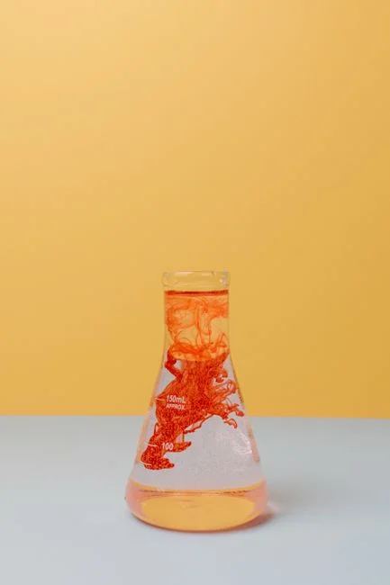
Coagulant choice is the variable the Water Science & Technology study (2001) found most influential for hydrocarbon removal on petrochemical feeds. The comparison below is the one buyers and EPC engineers should put in front of jar-testing labs.
| Conditioning Chemical | Mechanism | Strengths on Oily Streams | Limitations |
|---|---|---|---|
| Aluminum sulfate (alum) | Charge neutralization | Widely available, well-understood chemistry | Generates more chemical sludge; pH-sensitive; weaker on bridging emulsified oil droplets |
| Cationic polyelectrolyte | Charge neutralization + polymer bridging | Often more effective per dose on oily streams because it neutralizes charge and bridges droplets | Higher cost per kilogram; requires correct dose and mixing to avoid overdose and restabilization |
Alum works through charge neutralization, but it generates more chemical sludge and is pH-sensitive (Water Science & Technology, 2001). Cationic polyelectrolytes are frequently more effective per dose on oily streams because they combine charge neutralization with polymer bridging, but they cost more and demand tighter dose control (Water Science & Technology, 2001). Jar testing on the actual plant influent is the necessary first step before specifying any coagulant or polymer, as feed chemistry changes with different feedstocks. pH adjustment with acid or base is normally required ahead of the coagulant dose to put the stream inside the chemistry's working window (Clearwater Industries).
Placing DAF in a Petrochemical Wastewater Treatment Flowsheet
A reference flowsheet for a refinery or petrochemical complex looks like this: source → equalization → API or CPI separator (gravity oil removal) → DAF (emulsified oil, fine TSS, flocculable hydrocarbons) → biological (activated sludge, MBBR or SBR) → tertiary clarification → disinfection or reuse (Water Science & Technology, 2001; Clearwater Industries). The DAF effluent must meet the tolerance of the biological stage; DAF reduces load but does not produce a final discharge.
For plants with limited footprint, a compact skid-mounted DAF with integrated chemical conditioning shortens installation and reduces the number of field interfaces. The surface sludge skimmed from the DAF is routed to a dewatering step—commonly a plate-and-frame filter press—before the cake is sent to disposal or incineration. Integrating sludge handling into the early flowsheet layout prevents the DAF from being approved without a defined downstream path for the float, which is a common retrofit problem on older sites.
2026 Supplier Selection Checklist for a Petrochemical DAF
The first decision is whether the vendor can hit your flow rate on a standard model rather than a custom build; the HydropureWater DAF line covers 4–300 m³/h across 13 standard models, spanning a single petrochemical process train from a small specialty plant to a large integrated complex (HydropureWater product catalog). Ask for documented removal data on oily and hydrocarbon-laden feeds at A/S ratios similar to your design point, rather than municipal or food-industry references (Water Science & Technology, 2001). Request proof that the unit generates micro-bubbles within the 30–50 micron window and confirmation of operating pressure capability in the 40–70 psi range (Clearwater Industries; HydropureWater technical article).
Verify that the chemical conditioning skid is integrated or supplied as a matched package, including pH adjustment, coagulant dosing, and polymer dosing, with a clear flash-mix contact-time window in the 15–45 second band (Clearwater Industries). Clarify the sludge handling interface—surface scum concentration, expected dryness, and how the float integrates with downstream dewatering. Lead time and price depend on the model selected, whether the chemical skid is integrated, and documentation requirements; request these as line items rather than a single lumped figure. For a structured walk-through of unit selection, the 2026 DAF unit selection framework and the DAF oil-water separator guide cover the questions a vendor should be able to answer. For long-term operability, the DAF maintenance protocol lists the O&M items a supplier should hand over with the unit.
Frequently Asked Questions
What does a DAF system actually remove from petrochemical wastewater?
DAF removes free oil, emulsified oil (after chemical conditioning), suspended solids, hydrocarbons, and phenols; it is positioned as the pre-treatment step in front of the biological stage, not as a final polisher (Water Science & Technology, 2001; Clearwater Industries). DAF does not remove dissolved salts, ammonia, or refractory organics; those are the biological and tertiary stages' job.
Can a DAF replace an API separator in a refinery flowsheet?
No. The API separator handles bulk free oil by gravity, and DAF sits downstream of it, targeting the emulsified oil and fine solids the API separator cannot catch (Water Science & Technology, 2001; Clearwater Industries). Removing the API separator from a flowsheet design is a common shortcut that almost always causes emulsified oil breakthrough at the DAF and shock loading on the biological stage.
How do you size a DAF for a refinery or petrochemical plant?
Sizing starts with peak and average flow rate, then layers in influent pollutant load, target A/S ratio, and the chemistry window for the chosen coagulant; the standard catalog range of 4–300 m³/h covers most single-train applications (HydropureWater product catalog). Before the model is frozen, jar testing on the real plant influent is required to set flocculant type, dose, and A/S ratio (Water Science & Technology, 2001).
What coagulant works best for oily wastewater, and what does a 2026 DAF installation cost?
Alum and cationic polyelectrolyte are the two conditioning chemistries compared in academic studies on petrochemical wastewater; cationic polymer is often more effective per dose on oily streams because it both neutralizes charge and bridges droplets, but jar testing on the actual feed is the deciding step (Water Science & Technology, 2001; Clearwater Industries). As pricing depends on flow rate, material of construction, integration scope, and lead time, the buyer should request a written quote that itemizes the unit, chemical conditioning skid, sludge dewatering interface, and documentation package.
Related Equipment
- automatic chemical dosing system — specifications, capacity range, and technical data