
What "best" means for a 2026 UPW distribution loop
The best piping system for a semiconductor UPW distribution loop in 2026 is one that simultaneously holds the SEMI F63 / ASTM D5127 envelope at the point of use and resists biofilm formation along every meter between the polishing skid and the tool. Those two standards — SEMI F63 for semiconductor water quality and ASTM D5127 for electronics and semiconductor UPW, with ISO 3696 Grade 1 as a useful supplementary reference — set the binding numbers the pipe must not compromise: resistivity >18.2 MΩ·cm at 25 °C, TOC <1 ppb at the point of use for current production nodes, and <0.5 ppb TOC for 2 nm and 3 nm nodes per AXEON Water (2025). AXEON's parameter table also lists dissolved silica at 0.2–1.0 ppb, colloidal silica at 0.3–2.0 ppb, and particles (>0.05 µm) at <0.3 particles/mL measured by laser particle counter, with bacteria <1 CFU/100 mL by membrane filtration.
Resistivity alone is not a sufficient release criterion. Wikipedia's UPW entry notes that 0.1 ppb of NaCl already drops resistivity to 18.11 MΩ·cm (0.05523 µS/cm), so ionic breakthrough can be invisible until downstream particle and silica counters move first. That is why the same AXEON table pairs resistivity with TOC, dissolved silica, colloidal silica, and an inline particle count — they are checked as one envelope, not four independent specs. The feedwater feeding the loop is itself tight: TOC <5 µg/L, bacteria <1 CFU/100 mL, and particles <200 particles/L per the S3 biostability study (Desalination, 2024).
| Parameter | Specification at POU | Measurement method |
|---|---|---|
| Resistivity | >18.2 MΩ·cm at 25 °C | Inline conductivity meter |
| TOC | <1 ppb (current nodes); <0.5 ppb (2/3 nm) | UV-persulfate oxidation |
| Silica (dissolved) | 0.2–1.0 ppb | ICP-MS |
| Silica (colloidal) | 0.3–2.0 ppb | ICP-MS |
| Particles (>0.05 µm) | <0.3 particles/mL | Laser particle counter |
| Bacteria | <1 CFU/100 mL | Membrane filtration |
| Dissolved oxygen | <10 µg/L (semiconductor rinse) | Electrochemical or optical fluorescence |
Why pipe material and jointing are now first-tier UPW decisions
The distribution loop is not plumbing bolted onto a polishing skid — it is a contamination source that can undo the train. The S3 study (Desalination, 2024) reports that "nearly all high-purity water piping systems form biofilms over time" and that biofilm, not feedwater, is the dominant bacterial source in UPW. In the loop the authors sampled, the bacterial community was 66.15% Ralstonia, a nitrogen-fixing and ureolytic organism that formed significant biofilm on stainless steel (SUS) and CPVC pipe walls. That single finding is the reason pipe selection is no longer a downstream purchasing decision — it is a yield decision.
Organic carbon and particles arrive from the loop in three documented ways. First, plastic piping leaches TOC directly into the water, and the same AXEON article (2025) lists "leaching from plastic piping" alongside bacteria and dissolved atmospheric CO₂ as the three principal organic-carbon sources. Second, particles in UPW originate partly from the walls of the fluid handling system itself, including bacterial fragments shed from biofilm (Wikipedia, UPW). Third, the culture-based heterotrophic plate count (HPC) method used in fabs captures only about 1% of viable bacteria, because most UPW organisms exist in a viable but non-culturable (VBNC) state — the S3 paper recommends replacing HPC with flow cytometry (FCM) for that reason.
Jointing is the other half of the equation. Elastomeric gaskets and threaded adapters are a documented TOC and particle source because the elastomer itself leaches and the crevice traps bacteria. Continuous, seal-free joints — orbital butt fusion or IR fusion for thermoplastics, autogenous orbital TIG with full penetration for stainless — eliminate both the elastomer and the crevice, which is why they are now specified at the same time as the pipe material. Skipping jointing in the spec and fixing it on the skid is a common cause of biofilm returns within the first 12 months of operation.
Pipe material comparison: PVDF, PP, SUS, CPVC, PVC
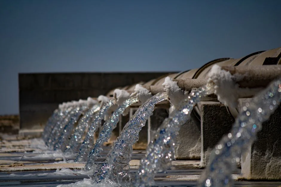
The S3 study is the only source in the research set with comparative pipe-material data, and it is qualitative rather than numeric, so the matrix below is built as a side-by-side rather than a scored table. Five materials are evaluated: PVDF (polyvinylidene fluoride), PP-H (homopolymer polypropylene), SUS (typically 316L electropolished stainless steel), CPVC (chlorinated polyvinyl chloride), and PVC (included in S3 only as a drinking-water baseline).
PVDF had the lowest documented TOC leaching and biofilm formation in the S3 study and is the default for new sub-7 nm loops; it is compatible with orbital butt fusion and IR fusion welding, which matches the jointing spec above. PP-H is a lower-cost thermoplastic with a smooth bore and good weldability; it is widely used in EU fabs where the TOC target is 1 ppb rather than 0.5 ppb. SUS retains its place where mechanical performance and high-temperature capability matter, but the S3 paper documents significant Ralstonia biofilm on SUS, so it needs aggressive sanitization and tight dead-leg control to remain acceptable. CPVC also showed significant biofilm in S3. PVC is not appropriate as a primary UPW loop material; it appears in S3 only as a baseline against drinking-water conditions.
| Material | TOC migration tendency | Biofilm tendency (S3) | Preferred jointing | Typical 2026 use |
|---|---|---|---|---|
| PVDF | Lowest in S3 comparison | Lowest in S3 comparison | Orbital butt fusion; IR fusion | Default for sub-7 nm loops; POU mains |
| PP-H | Low | Low | IR fusion; socket fusion (low-leach) | EU fabs at 1 ppb TOC target |
| SUS (316L EP) | Low ionic, depends on passivation | Significant Ralstonia biofilm (S3) | Autogenous orbital TIG, full penetration | High-temperature sections; tool drops |
| CPVC | Moderate | Significant biofilm (S3) | Solvent cement (not preferred for UPW) | Limited; retrofit only with controls |
| PVC | Higher | Drinking-water baseline (S3) | Solvent cement | Not for primary UPW loop |
The final final 0.2 µm point-of-use filter elements on the loop are part of the same spec as the pipe: the pipe determines how clean the filter stays, and AXEON (2025) and Wikipedia both list 0.2 µm (≤200 nm) final filters at POU as standard. Where reclaimed or seawater feedstocks push small-molecule organics through RO and IX, a 0.03 µm PVDF ultrafiltration stage upstream of the loop reduces the biodegradable load that feeds biofilm downstream.
Engineering specification for the loop itself
Material is only one of the two coupled variables the S3 paper calls out — hydraulic conditions are the other. The loop must be recirculated continuously, and Wikipedia's UPW entry states that UPW is "typically cycled continuously through the polishing system to prevent stagnation that can lead to bacterial growth." Stagnation in a dead leg is the most common root cause of a biofilm return on a loop that otherwise passes resistivity. The S3 conclusion is explicit: "stringent ultrapure water (UPW) quality standards require high-quality pipe materials and well-controlled hydraulic conditions to prevent biofilm formation" (cited work, Desalination, 2026).
Particle control is a second hydraulic lever. Wikipedia notes that "particles must be filtered down to a 'critical particle size' that is one-half of the smallest feature size on a semiconductor chip," and gives the working example that 40 nm features require removal of all particles above 20 nm (0.02 µm). That sets the upper bound for any shed particle or biofilm fragment: the loop spec must keep shedding below the feature size, not just below the AXEON 0.05 µm particle counter trigger. The monitoring framework described by AXEON — inline resistivity, TOC analyzers, and particle counters feeding PLC alarms on pressure and flow — is the loop-level instrumentation spec, and a 185 nm / 254 nm UV sterilizer on the return loop supports continuous TOC reduction in the recirculated stream.
Jointing must be specified at the same time as the pipe. For thermoplastics, prefer orbital butt fusion or IR fusion; both eliminate the elastomeric seals that are a documented TOC and particle source. For stainless sections, specify autogenous orbital TIG with full penetration and documented passivation. The research set does not give a numeric passivation standard or a numeric dead-leg length, so the buyer should request those limits as part of the supplier's weld procedure qualification record rather than assume a value.
2026 procurement and qualification checklist
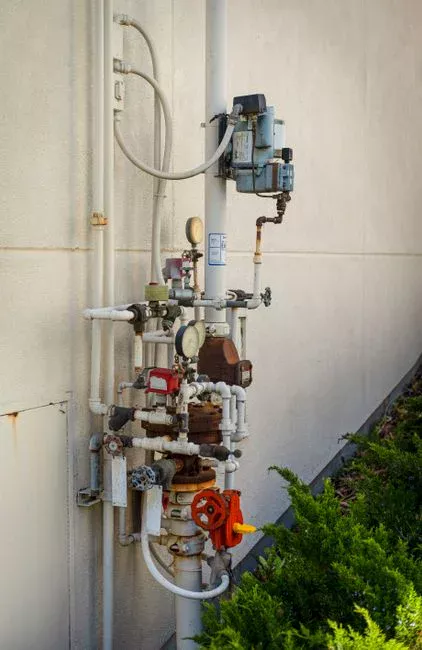
The technical argument above only protects the fab if it lands in the purchasing document. The first contractual line item is per-material extractables / TOC migration data on the actual production lot, not generic datasheets — the S3 paper makes the case that low-feedwater TOC does not guarantee low loop TOC, so generic compliance certificates are not enough. The second is a weld procedure qualification record for the orbital or IR fusion joints being installed, plus a documented passivation and sanitization plan for any metallic section in the loop.
Biofilm control is the third line item, and it has to be specified by method. Ask suppliers to demonstrate biofilm control using flow cytometry (FCM), which the S3 study proposes as a replacement for HPC because the culture-based method undercounts by roughly 99% (Desalination, 2024). A supplier that can only quote HPC numbers is quoting from a method that cannot see the problem. The fourth item is reclaimed- or seawater-feedstock compatibility: Wikipedia's UPW entry notes that urea and other small-molecule organics "are not effectively removed by conventional ion exchange, reverse osmosis, or ultraviolet treatment," so the pipe material must not be the weak link in a feedstock that is already pushing the polishing train. A final industrial RO unit ahead of the polishing train reduces the biodegradable load the loop sees, and electrodeionization polishing holds resistivity at the skid outlet.
| Line item | What to require from the supplier | Why it matters (source) |
|---|---|---|
| Extractables / TOC migration data | Lot-specific, not generic datasheet | Low-feedwater TOC does not guarantee low loop TOC (S3, 2024) |
| Weld procedure qualification | Orbital or IR fusion PQR; passivation plan for SUS | Elastomeric seals are a TOC and particle source (qualitative) |
| Biofilm control method | Flow cytometry (FCM), not only HPC | HPC captures ~1% of viable bacteria (S3, 2024) |
| Feedstock compatibility | Reclaimed/seawater track record, small-molecule organics handling | Urea and similar organics survive RO/IX/UV (Wikipedia, UPW) |
| End-of-loop quality targets | >18.2 MΩ·cm, <1 ppb TOC, <0.3 particles/mL at 0.05 µm | SEMI F63 and ASTM D5127 envelope (AXEON, 2025) |
The fifth and last contractual line is the end-of-loop quality target itself: >18.2 MΩ·cm, <1 ppb TOC, <0.3 particles/mL at 0.05 µm, tied explicitly to SEMI F63 and ASTM D5127. Engineers specifying a new fab or retrofit should also flag the related chip fab wastewater cost breakdown and the GaN fab wastewater cost guide for the discharge side of the same project.
Frequently Asked Questions
Which pipe material actually keeps biofilm off a UPW loop?
The S3 biostability study (Desalination, 2024) found that Ralstonia — a nitrogen-fixing and ureolytic bacterium — formed significant biofilm on stainless steel (SUS) and CPVC pipe walls, accounting for 66.15% of the bacterial community in the loop sampled. PVDF showed the lowest biofilm tendency in the same comparison and is the default for new sub-7 nm loops; PP-H is a lower-cost alternative where the TOC target is 1 ppb rather than 0.5 ppb.
How do I keep reclaimed or seawater feedstock from breaking the loop spec?
Wikipedia's UPW entry notes that reclaimed water "typically contains higher levels of small-molecule organic pollutants such as urea, which are not effectively removed by conventional ion exchange, reverse osmosis, or ultraviolet treatment." The pipe material must not be the weak link in that envelope — specify PVDF or PP-H for the loop, push the polishing train with an industrial RO unit and electrodeionization polishing, and require FCM-based biofilm monitoring rather than relying on HPC alone.
What is a defensible cost-vs-performance trade-off when buying UPW loop piping?
PVDF commands a material premium over PP-H and over 316L electropolished stainless, but the S3 results (Desalination, 2024) show that SUS and CPVC carry documented Ralstonia biofilm risk that drives ongoing sanitization cost and yield risk. For a sub-7 nm or 2/3 nm node where the TOC target drops to <0.5 ppb (AXEON, 2025), the defensible position is PVDF on the POU mains and on any section that cannot be aggressively sanitized; PP-H is defensible for a 1 ppb node where the fab already has a sanitization protocol. The research set does not contain a per-meter price, so request a lot-specific quote with weld procedure qualification records and TOC migration data attached before committing.
How do I qualify a UPW piping supplier in 2026?
Require three things on the supplier side: (1) lot-specific extractables or TOC migration data on the actual production run, not a generic datasheet — S3 makes the case that low-feedwater TOC does not guarantee low loop TOC; (2) weld procedure qualification records for the orbital or IR fusion being installed, plus a documented passivation plan for any stainless section; (3) biofilm control demonstrated by flow cytometry (FCM), because the culture-based HPC method captures only about 1% of viable bacteria in UPW (S3, Desalination, 2024). A supplier that can only quote HPC numbers or generic compliance certificates is not qualified to be the long-loop supplier for an advanced node.