
Why Water Is Now a Board-Level Issue for US Hyperscale Sites
Hyperscale data centers — campuses typically built and operated by AWS, Google, Microsoft and Meta — are no longer just an MEP detail in a sustainability report. AI training clusters have pushed rack densities and continuous cooling duty into a range where water demand intersects with local utility stress, ESG disclosure and state-level siting rules, which is why a hyperscaler's water strategy now sits on the same board slide as its power contract.
Two key performance indicators govern the conversation, and they are not interchangeable. Power Usage Effectiveness (PUE) measures the energy overhead of the compute load, while Water Usage Effectiveness (WUE) measures the water intensity of the cooling system, expressed in litres of water per kWh of IT load (Cheng & Zhou, AJAGE, 2024). The 2024 review of US hyperscaler water strategies frames PUE and WUE as the two governing KPIs and maps them against the UN 2030 Sustainable Development Goals — the same lens ESG teams, utilities and permitting authorities apply to new campuses.
The engineering consequence is that "just chill it harder" is no longer a defensible posture. Whether a site is being green-fielded or retrofitted, the design conversation must start from a public water target, move into the cooling architecture that can credibly hit that target, and finish on the on-site water-treatment train that keeps the architecture reliable on non-potable or recycled feed. The hyperscaler strategies published between 2021 and 2022, and synthesised in the 2024 review, define the "why"; the cooling architectures and the treatment train define the "how."
How Hyperscalers Are Framing Water Efficiency in 2026
The 2024 review by Cheng & Zhou groups US hyperscaler water strategies into two camps: volumetric Water Positive / replenishment targets and cooling-side efficient-cooling strategies. These camps provide the public baseline for 2026 implementations and remain standard for internal design-review slides.
Amazon's position is anchored by the AWS Water Positive Methodology (Amazon, 2022), in which AWS commits to returning more water to communities than it uses in its direct operations, as cited in Cheng & Zhou (2024). Google's water strategy, set out in the Google Water Stewardship report (Google, 2021-09), puts the emphasis on water replenishment in the basins where it operates (Cheng & Zhou, 2024). Microsoft, in its datacenter water-consumption fact sheet (Microsoft, 2021-11), and Meta, in the Meta 2021 Sustainability Report (2022-06), both lean on the second camp — efficient cooling systems — as the primary operational lever toward their water goals (Cheng & Zhou, 2024).
Two practical notes for a 2026 design review. First, the Cheng & Zhou review is dated 2024, but the underlying hyperscaler documents it cites are 2021–2022, so treat the strategies as the public baseline rather than the latest operational benchmark; the current revision of each hyperscaler's water report should be requested before any number is written into a permit application. Second, none of the four sources publish a single numeric WUE benchmark — WUE is treated as a relative KPI for comparison across sites, not a published target you can copy into a spec.
| Hyperscaler | 2026 water strategy framing | Underlying public document (as cited by Cheng & Zhou, 2024) | Document date |
|---|---|---|---|
| Amazon (AWS) | Volumetric Water Positive | AWS Water Positive Methodology | 2022 |
| Water replenishment in operating basins | Google Water Stewardship report | 2021-09 | |
| Microsoft | Efficient-cooling-led strategy | Microsoft datacenter water-consumption fact sheet | 2021-11 |
| Meta (Facebook) | Efficient-cooling-led strategy | Meta 2021 Sustainability Report | 2022-06 |
The Three Cooling Architectures That Actually Move the WUE Needle
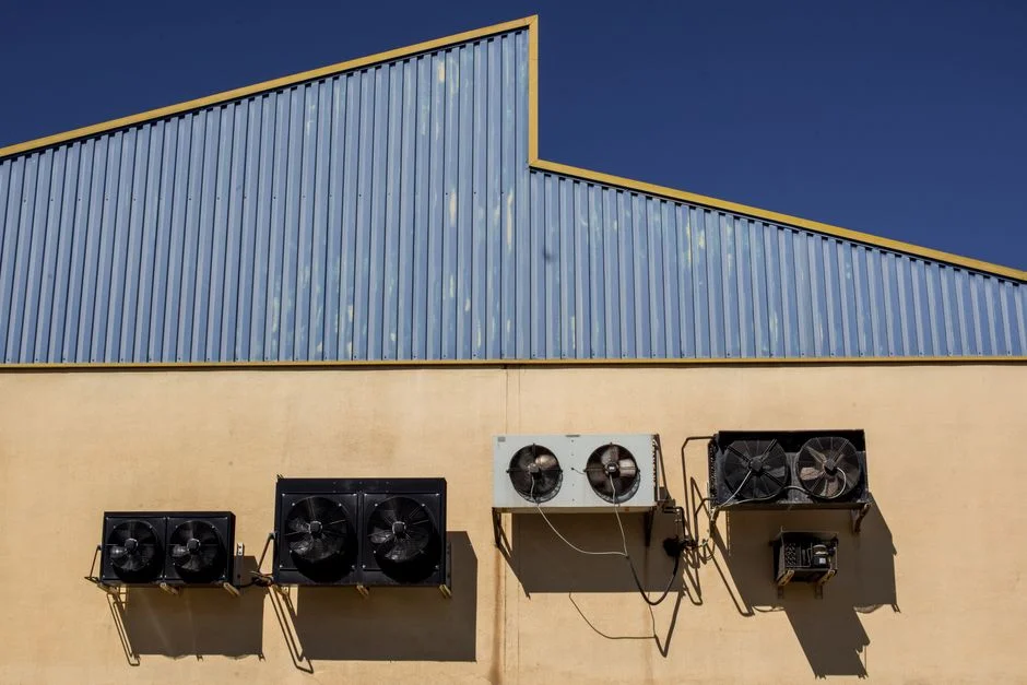
There are three cooling families a 2026 US hyperscale design review will weigh against each other. Each one trades water for energy, capex and site constraints, and each one changes the load profile that the on-site water-treatment train has to support.
Liquid-cooled architectures — cold-plate / direct-to-chip and single- or two-phase immersion — capture heat in a dielectric or treated water-glycol loop and reject it through a facility water loop, almost always via a liquid-to-liquid heat exchanger. Because evaporation is removed from the IT side, WUE drops sharply, but the facility loop still needs scale, corrosion and microbial control and a treatment train that can handle the closed-loop chemistry. Hybrid adiabatic / evaporative systems combine a refrigerant or chilled-water path with adiabatic pre-cooling of the intake air, cutting compressor energy but reintroducing evaporative loss whose magnitude is governed by cycle of concentration and the local ambient wet-bulb. Air-cooled economizer architectures use outside air directly to carry IT heat whenever temperature and humidity allow, which gives the lowest WUE of the three at the cost of climate dependency and a hard ceiling on IT-rack inlet temperature.
Across all three, the engineering parameters the treatment train must support are the same family: evaporative loss as a function of ΔT across the loop, drift rate at the tower, and the blowdown fraction set by the cycle of concentration. The Cheng & Zhou (2024) review presents WUE as a relative KPI rather than publishing a single numeric benchmark, so any absolute WUE target in a 2026 spec has to be sourced from the chosen hyperscaler's most recent disclosure.
| Architecture | Dominant WUE lever | Water-side engineering parameters | Climate and workload fit |
|---|---|---|---|
| Liquid-cooled (cold-plate / immersion) | Removes most evaporation from the IT side | Closed-loop chemistry on the facility water loop, heat-exchanger fouling control, side-stream filtration | High-density AI training clusters; any US climate |
| Hybrid adiabatic / evaporative | Cycle of concentration, ambient wet-bulb | ΔT across loop, drift rate, blowdown fraction, Legionella control | Mixed US climates; general-purpose cloud capacity |
| Air-cooled economizer | Lowest fresh make-up demand | Air-side filtration, humidification control, IT inlet-temperature envelope | Dry / cool US sites (e.g. Pacific Northwest, Upper Midwest); limited as sole carrier for AI training |
Designing the Reuse-Grade Water Treatment Train
Every one of the three cooling architectures above is only as water-efficient as the treatment train behind it. A tighter loop with higher cycles of concentration, or a feed that has been blended with reclaimed municipal or cooling-tower blowdown water, changes the influent profile that hits the membranes, the tower and the disinfection stage. The reuseinn.com piece on data-center water reuse (S5) frames wastewater reuse as the emerging cooling-water source for data centers, which is the qualitative direction a 2026 spec must follow. Four stages cover the chain.
Stage 1 — Make-up pretreatment. A multi-media pretreatment filter for hyperscale cooling make-up water sits ahead of the membranes, removing suspended solids and turbidity spikes so downstream RO and UF are not damaged by SDI excursions. The filter must be sized for the make-up flow, the expected turbidity envelope, and the backwash water it will produce. Stage 2 — Membrane polishing. A 0.03 μm PVDF hollow-fiber ultrafiltration system for cooling-loop side-stream filtration operates in the 2,000–40,000 L/h range, accepts up to 300 ppm turbidity on the feed, and runs automatic backwash and air scour, making it suitable either as RO pretreatment or as direct side-stream filtration on the cooling loop. Stage 3 — Blowdown handling. Cooling-tower blowdown should be specified as a recoverable stream — not a waste stream — and routed either back through the UF / RO polishers for reuse, or to an on-site industrial water reclaim line. Stage 4 — Disinfection. A EPA / EU / WHO-compliant ClO₂ generator for cooling-loop microbial control is sized across the 50 g/h to 20,000 g/h generation range, compliant with EPA drinking-water requirements, EU Drinking Water Directive 98/83/EC, and the WHO Guidelines for Drinking-water Quality, which is what the cooling loop needs for Legionella and biofouling control when cycles of concentration are pushed higher to save water.
The hyperscaler strategies from the Cheng & Zhou (2024) review only become engineering reality once these four stages are sized against the new feed-water profile; a tighter cycle without the matching pretreatment and disinfection is the most common path to biofouling, scale and a Legionella event.
Selecting the Right Architecture for a US Hyperscale Site
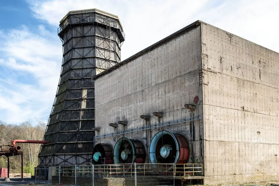
There is no single right answer for a 2026 US hyperscale site, but the decision can be narrowed to three filters applied in a design review.
First, filter by climate. Dry and cool US sites — Pacific Northwest, Upper Midwest — can lean on air-cooled economizer for a larger share of the year, with hybrid adiabatic as a shoulder-season bridge. Hot-humid sites — Gulf Coast in particular — have a much shorter free-cooling window and a much higher wet-bulb, which pushes the choice toward liquid or hybrid with high cycles of concentration. Second, filter by workload. AI training clusters with sustained high heat density are increasingly specified with direct-to-chip or immersion cooling, where the WUE benefit is largest; general-purpose cloud capacity remains a good fit for hybrid adiabatic. Third, filter by water-stressed basin. Where the operator has committed to a Water Positive or replenishment target, the cooling-side efficient-cooling strategy that Cheng & Zhou (2024) attributes to Microsoft and Meta is the most defensible operational lever — but it is only defensible if the treatment train is sized to the new feed-water profile, not the original potable spec.
For any of the three, the rule is the same: design the water-treatment train to match the architecture, not the other way around. Reuse targets and tighter cycles of concentration are only credible if pretreatment, blowdown handling and disinfection are specified together. The Cheng & Zhou (2024) review does not publish a single numeric WUE benchmark, so before any number goes into a permit, the latest WUE value should be confirmed against the chosen hyperscaler's current disclosure and the current revision of the AWS Water Positive methodology.
Frequently Asked Questions
What is the difference between PUE and WUE for a hyperscale data center?
PUE measures the energy overhead of the IT load, while WUE measures the water intensity of the cooling system in litres of water per kWh of IT load. The Cheng & Zhou (2024) review treats PUE and WUE as the two governing KPIs for hyperscaler water strategy and maps them against the UN 2030 Sustainable Development Goals.
Which US hyperscalers are actually pursuing Water Positive in 2026, and how?
Per the Cheng & Zhou (2024) review, Amazon is pursuing a volumetric Water Positive commitment under the AWS Water Positive Methodology (2022), Google is pursuing basin-level water replenishment per the Google Water Stewardship report (2021-09), and Microsoft and Meta are pursuing Water Positive primarily through efficient-cooling-led strategies, as documented in the Microsoft datacenter water-consumption fact sheet (2021-11) and the Meta 2021 Sustainability Report (2022-06). The latest revision of each hyperscaler's public water report should be requested before any target is written into a 2026 permit, since these are the baseline documents the original commitments are measured against.
Which cooling architecture is the most water-efficient for a US hyperscale site?
For a given site, the answer depends on climate and workload: liquid-cooled (direct-to-chip and immersion) generally gives the lowest WUE because it removes most evaporation, hybrid adiabatic / evaporative sits in the middle and is governed by cycle of concentration and ambient wet-bulb, and air-cooled economizer gives the lowest fresh make-up demand but is climate-bound. Cheng & Zhou (2024) present WUE as a relative KPI rather than a single numeric benchmark, so the actual WUE target should be confirmed against the