A primary clarifier maintenance guide should include 7 key steps: inspect weirs monthly, clean launders weekly, monitor sludge blanket depth daily, service drive assemblies annually, replace seals every 2–3 years, prevent algae with opaque covers, and conduct full mechanical inspections every 12–18 months to prevent short-circuiting and maintain 50–65% TSS removal efficiency.
Why Primary Clarifier Maintenance Prevents Costly Downtime
Regulatory fines for wastewater discharge violations can reach up to $10,000 per day under EPA Clean Water Act mandates when primary treatment systems fail to meet effluent standards. The primary clarifier serves as the first major defense in the treatment process; when it underperforms, the entire facility suffers. Specifically, poor primary clarification can reduce Total Suspended Solids (TSS) removal from an optimal 50–65% to below 40%, which significantly increases the organic and hydraulic load on secondary biological systems (per EPA guidelines). This downstream "shock" often leads to secondary process failure, requiring expensive reseeding of activated sludge or increased aeration energy costs.
Mechanical failure is the most common cause of this performance drop. Industry data indicates that drive failure accounts for 40% of unplanned clarifier outages (WesTech Engineering, 2016). When a rotating clarifier mechanism seizes, the sludge blanket quickly accumulates, leading to anaerobic conditions, gas production, and "bulking" where solids rise to the surface and exit via the effluent weir. Beyond the immediate repair costs, which can exceed $50,000 for large drive assemblies, the operational downtime forces plants to bypass primary treatment or overload remaining units, risking permit violations.
Proactive maintenance is not merely about avoiding repairs; it is about protecting the asset's lifecycle. A well-maintained clarifier can operate for 30–40 years, whereas a neglected unit may require a full structural rebuild in less than 15 years due to accelerated corrosion and mechanical strain. By following a structured primary clarifier maintenance guide, operators shift from reactive crisis management to a predictive model that ensures consistent compliance and minimal operational expenditure.
Step 1: Inspect and Maintain the Effluent System Weekly
Effluent weir levelness must be maintained within a tolerance of ±1/8 inch across the entire circumference of the tank to ensure even flow distribution and prevent localized high-velocity zones. When weirs are not level, water flows preferentially over the lower sections, creating a "pull" that draws solids upward from the sludge blanket—a phenomenon known as short-circuiting. Operators should use a transit or laser level annually to verify this, but weekly visual inspections are required to identify localized shifting or debris buildup.
Cleaning V-notched weirs and launders weekly using stiff brushes is essential to remove accumulated biofilm and inorganic debris. If left uncleaned, algae and slime build up on the weir edges, effectively changing the notch geometry and causing uneven flow. To inhibit this growth, operators may apply a low-dose chlorine solution (1–2 ppm) during the cleaning process. This is particularly critical in open-air clarifiers where sunlight promotes rapid photosynthesis. For facilities struggling with persistent biological growth, installing opaque launder covers can block light and reduce algae formation by up to 90% (WesTech), significantly reducing the labor required for manual scrubbing.
In addition to cleaning, the weekly weir cleaning procedure should include an inspection of the scum baffle. The baffle must be securely fastened and positioned to prevent floating oils, grease, and plastics from escaping into the effluent launder. Any gaps between the baffle sections or between the baffle and the tank wall must be sealed immediately. Ensuring the integrity of the effluent system is the simplest way to maintain high TSS removal rates and protect downstream processes, such as a 7-step maintenance guide for advanced secondary treatment systems.
Step 2: Monitor and Control Sludge Blanket Depth Daily
The ideal sludge blanket depth in a circular primary clarifier is 2–4 feet, providing sufficient thickening time without risking solids carryover. Measuring this depth daily is the most critical task for an operator. This can be performed manually using a "sludge judge" (a clear plastic tube with a check valve) or a weighted tape, though many modern plants now utilize ultrasonic sensors for continuous monitoring. If the blanket depth exceeds 5 feet, the risk of buoyancy increases; as sludge ferments, it releases gases that can cause large clumps of solids to rise to the surface.
When the blanket becomes too deep, the operator must increase the sludge withdrawal rate immediately. However, this must be balanced carefully. Excessive pumping can lead to "rat-holing," where water is pulled through the sludge layer, resulting in thin, watery sludge that is difficult to dewater. Conversely, maintaining a blanket that is too shallow (less than 1 foot) reduces the concentration of the underflow, increasing the volume of water that must be handled by solids processing equipment.
Short-circuiting in clarifiers often occurs when the influent bypasses the intended settling zone due to poor sludge removal or internal seal leaks (WesTech). Monitoring the sludge blanket depth allows operators to detect these issues before they manifest as cloudy effluent. If the blanket is uneven—deeper on one side than the other—it often indicates a mechanical issue with the rake arm or a hydraulic imbalance in the influent well. Consistent daily logging of these levels provides the data necessary to calibrate sludge pumps and optimize the performance of the entire solids handling train.
Step 3: Service the Sludge Removal System Every 6 Months
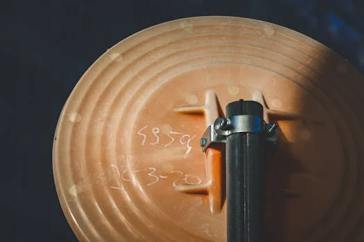
Squeegee blades on the rake arms must be inspected every 6 months and adjusted to maintain a 1/8-inch contact gap with the tank floor to ensure efficient solids transport to the center hopper. Over time, these blades wear down or become bent due to debris. If the gap becomes too large, a layer of "stale" sludge will remain on the floor, leading to septic conditions and odors. During this semi-annual check, technicians should also inspect the fasteners and structural members of the rake arm for signs of corrosion or stress fractures.
In suction-header type clarifiers, the maintenance requirements are more technical. Rotating seals in suction clarifiers should be replaced every 2–3 years to prevent short-circuiting from leaky joints. If these seals fail, the vacuum created by the suction header will pull clarified water from the upper layers instead of concentrated sludge from the floor. Additionally, suction header plugging is a frequent issue in industrial settings with high fiber or plastic content. Technicians should flush riser pipes and header orifices annually to remove debris. Zhongsheng field data suggests a standard flush pressure of 5–10 psi for a 30-minute cycle to effectively clear internal blockages.
The efficiency of the sludge removal system directly impacts the performance of dewatering equipment. If the clarifier is not producing a consistent underflow concentration, it can cause significant issues for a plate and frame filter press, leading to longer cycle times and wetter cakes. Maintaining the mechanical integrity of the rake system ensures that the sludge delivered to the next stage is as concentrated and uniform as possible.
Step 4: Maintain the Clarifier Drive Assembly Annually
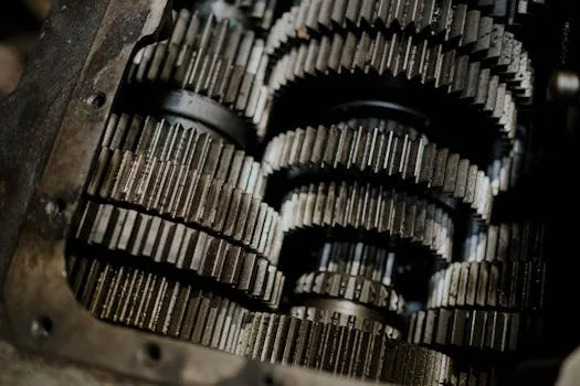
The drive assembly is the heart of the clarifier, and its failure results in immediate and total system downtime. Annual maintenance must include a thorough inspection of the gearbox for oil level, contamination, and gear wear. Oil should be changed every 12–18 months, or more frequently if moisture is detected. Because these drives operate at very low RPMs but high torque, even minor lubrication failures can lead to catastrophic gear stripping. Vibration analysis conducted every 6 months can detect misalignment or bearing wear long before they are audible to the human ear.
Torque overload settings are the primary safety mechanism for the drive. These must be checked and calibrated annually to ensure the motor trips before mechanical damage occurs. If a rake arm encounters an obstruction or a massive sludge buildup, a properly calibrated sensor will shut down the system. Operators should also inspect the "bull gear" and pinion for proper lubrication and tooth engagement. According to an Evoqua webinar, most drive assemblies should be slated for a professional rebuild every 7–10 years, depending on the runtime and the grit load of the influent.
To keep the drive running smoothly, it is also important to ensure the influent is free of large debris that could jam the mechanism. Using a rotary mechanical bar screen at the headworks is a critical preventive measure that protects the clarifier drive from damaging solids. Below is a summary of the recommended drive maintenance intervals:
| Component | Action | Frequency | Threshold/Target |
|---|---|---|---|
| Gearbox Oil | Check & Sample | Monthly | No water/metal flakes |
| Drive Lubrication | Grease Bearings | Quarterly | Per manufacturer spec |
| Oil Change | Full Replacement | 12–18 Months | Synthetic or ISO 220 grade |
| Vibration Analysis | Measurement | 6 Months | < 0.3 in/sec RMS |
| Torque Sensor | Calibration | Annually | Trip at 100% design torque |
| Drive Assembly | Major Rebuild | 7–10 Years | Factory tolerances |
Step 5: Conduct Comprehensive Mechanical Inspections Every 18 Months
Draining the clarifier tank every 12–18 months is necessary to conduct a full structural and mechanical audit that is impossible while the unit is in service. Once the tank is drained and the surfaces are pressure-washed, the first priority is inspecting the concrete or steel floor for erosion, pitting, or sediment buildup in the hopper. In steel tanks, technicians should perform ultrasonic thickness testing on the walls to ensure structural integrity hasn't been compromised by corrosion. For concrete tanks, look for spalling or exposed rebar, particularly at the waterline where freeze-thaw cycles are most damaging.
The alignment of the rotating clarifier mechanism must be verified during this shutdown. Check the torque tube and rake arms for levelness; any misalignment greater than 2° requires immediate realignment to prevent uneven stress on the drive bearing. This is also the time to inspect the influent well (well-flector) and the center column for structural stability. If the influent well is loose or damaged, it will cause turbulence that destroys the quiescent settling environment needed for effective solids separation.
A structured inspection workflow should be followed: drain the tank, clean all surfaces, perform a visual check for mechanical wear, conduct thickness/integrity testing, and finally, develop a repair planning schedule. This proactive approach allows plant managers to budget for repairs during scheduled outages rather than reacting to emergency failures during peak flow periods. This level of detail is also common in a complete DAF system maintenance protocol for industrial applications, where internal components are subject to high wear.
Step 6: Prevent Algae and Corrosion with Coatings and Covers

Corrosion, erosion, and chemical attack are the three primary threats to the longevity of clarifier tanks and internal hardware. To combat this, high-performance epoxy coatings should be applied to launders, weirs, and any carbon steel components. These coatings not only protect the substrate but also create a smooth surface that reduces biofilm adhesion, making weekly cleaning much easier. In industrial environments where wastewater may have high chloride levels or extreme pH fluctuations, upgrading to stainless steel (Type 304 or 316) for weirs, scum baffles, and squeegee holders is a standard life-extension strategy.
Algae prevention is equally critical for effluent quality. Beyond chemical dosing, the use of opaque covers over the effluent launders is the most effective long-term solution. By eliminating sunlight, you remove the energy source for algae growth, which prevents weir plugging and the subsequent rise in TSS. In many cases, the reduction in labor costs for cleaning pays for the covers within 24–36 months. For plants with space constraints or high-rate requirements, a compact lamella clarifier for high-rate solids separation may be used, which often utilizes internal plate packs that also require specific coating protection to prevent fouling.
Maintaining the exterior of the drive and the bridge is also important. Rust on the bridge can flake off into the tank, potentially contaminating the sludge or damaging the squeegees. A routine "touch-up" painting program for any visible rust spots can prevent the need for expensive sandblasting and recoating of the entire structure later. In wastewater treatment, the environment is inherently corrosive; therefore, the selection of materials and the maintenance of protective barriers are the most effective ways to avoid premature capital replacement.
Step 7: Optimize Performance with Automation and Sensors
Modernizing a primary clarifier with automated sensors can reduce manual labor by up to 50% while improving effluent consistency. Installing ultrasonic sludge blanket sensors allows for real-time tracking of solids accumulation. When integrated with a PLC (Programmable Logic Controller), these sensors can automatically trigger sludge withdrawal pumps when the blanket reaches a pre-set height (e.g., 4 feet) and stop them once the blanket is lowered to the 2-foot target. This ensures the underflow concentration remains optimal and prevents the "human error" of over-pumping or under-pumping.
Automation also extends to chemical dosing. By integrating an automated chemical dosing to stabilize influent load, the plant can respond dynamically to changes in influent TSS or flow rate. For example, if an upstream process dump increases the solids loading, the PLC can increase coagulant dosing to maintain settling efficiency. This prevents shock loading from overwhelming the clarifier and ensures the facility remains in compliance even during industrial process upsets. For more on this, see our 12-step maintenance protocol for chemical dosing systems.
Finally, remote monitoring of drive torque and motor amperage provides an early warning system for mechanical issues. If the torque begins to trend upward over several weeks, it indicates a growing obstruction or a problem with the drive gears, allowing maintenance to be scheduled before a failure occurs. Transitioning from manual checks to sensor-based "smart" clarification is the hallmark of a modern, high-efficiency wastewater treatment plant.
Troubleshooting Common Primary Clarifier Problems
When performance drops, operators must be able to quickly diagnose whether the issue is hydraulic, biological, or mechanical. The following table provides a logic-based approach to the most common symptoms encountered in primary clarifier operations.
| Symptom | Potential Cause | Recommended Fix |
|---|---|---|
| Solids carryover in effluent | High sludge blanket or high influent flow | Increase sludge withdrawal rate; check for hydraulic surges. |
| Cloudy effluent (high turbidity) | Weir blockage or algae growth | Clean weirs/launders; check weir levelness; install covers. |
| Drive overload alarm | Misalignment, heavy sludge, or jammed rake | Check alignment; check for debris; decrease blanket depth. |
| Uneven sludge removal | Worn squeegees or leaking suction seals | Adjust squeegee height; replace seals in suction units. |
| Floating sludge clumps | Septic sludge (blanket too deep/old) | Increase pumping frequency; check for rake arm "dead spots." |
| Odors (Rotten egg/Sulfur) | Anaerobic conditions in the hopper | Flush sludge lines; increase withdrawal; clean scum pits. |
Frequently Asked Questions
How often should you clean a primary clarifier weir?
Weirs and launders should be cleaned weekly using stiff brushes and a low-dose chlorine solution to prevent algae buildup and ensure even flow distribution.What causes short-circuiting in a primary clarifier?
Short-circuiting is typically caused by unlevel effluent weirs, leaky seals in suction-header systems, or excessive influent velocity that disrupts the settling zone.How do you prevent algae in clarifier launders?
The most effective method is installing opaque launder covers to block sunlight. Regular weekly cleaning with chlorine also inhibits biological growth.When should you rebuild a clarifier drive?
A major rebuild is usually required every 7–10 years. However, if vibration levels exceed 0.3 in/sec RMS or if metal flakes are found in the oil, a rebuild should be scheduled immediately.What is the ideal sludge blanket depth in a primary clarifier?
The ideal depth is 2–4 feet. Allowing the blanket to exceed 5 feet increases the risk of solids carryover and anaerobic gas production.
Related Equipment
- compact lamella clarifier for high-rate solids separation — view specifications, capacity range, and technical data
Need a customized solution? Request a free quote with your specific flow rate and pollutant parameters.