Why Chemical Dosing System Maintenance Prevents Costly Failures
Routine chemical dosing maintenance is a 12-step industrial protocol covering LOTO, line flush, diaphragm and seal service, rate calibration to ≤ ±2%, valve and tubing checks, backpressure and anti-siphon tests, PLC signal validation, and a written log. Inspect diaphragms every 6 months; replace seals annually or every 2,000 operating hours on typical industrial duty.
Chemical dosing maintenance keeps metering accuracy inside process limits on wastewater and process-water skids. Under-dosing from poor calibration or worn wet ends can cut wastewater treatment efficiency by 40–60%, while over-dosing can raise chemical spend by up to 35% and push effluent outside permit limits. Industry benchmarks still point to pump seal failure as about 68% of unplanned dosing downtime: seal wear lets fluid reach the drive, then corrosion finishes the pump.
According to US OSHA 29 CFR 1910.147 (eCFR current as of September 2026), employers must isolate hazardous energy—including chemical energy—before servicing equipment where unexpected start-up or stored-energy release could injure workers. Step 1 of this protocol follows that lockout/tagout rule before any wet-end work.
Chemical Dosing Maintenance: 12-Step Industrial Protocol
A structured chemical dosing maintenance routine ties mechanical, electrical, and control checks into one shift-ready sequence. Most plants we size for sodium hypochlorite, coagulants, or pH control run the full wet-end strip at the lower end of the OEM interval when duty is continuous and the chemical is aggressive. Flushing lines (Step 2) clears crystals before they score seats; diaphragm inspection (Step 3) catches thinning before a rupture; calibration (Step 5) stops small stroke errors from compounding into under- or over-dose. Adjust frequency for chemical aggressiveness, ambient temperature, and manufacturer limits, but keep all twelve steps on the calendar.
| Step | Action | Frequency | Key Checks & Tolerances | Tools/Notes |
|---|---|---|---|---|
| 1 | Isolate Power and Chemical Supply | Before each maintenance session | Ensure compliance with OSHA 29 CFR 1910.147 (Lockout/Tagout). Verify zero energy state. Confirm that all associated valves are closed and locked to prevent accidental chemical release or power activation. | LOTO kit, safety signage, valve locking devices |
| 2 | Drain and Flush Lines | During each maintenance session | Use deionized water. Inspect for crystallization, a common issue in 90% of sodium hypochlorite systems. Ensure all residual chemical is removed to prevent damage to components and ensure safety during disassembly. Check for any signs of internal erosion or scaling within the lines. | Hoses, collection drum, PPE, flushing agent (if recommended for specific chemicals) |
| 3 | Inspect Diaphragm | Every 6 months | Look for cracks, bulging, thinning, or delamination. Replace if any compromise is found. Pay attention to the diaphragm's flexibility and any signs of hardening or brittleness, which can indicate early failure. Note any discoloration that might suggest chemical incompatibility. | Screwdriver, wrench, replacement diaphragm, inspection light |
| 4 | Replace Seals and O-rings | Annually or every 2,000 operating hours | Use only chemical-resistant materials (e.g., Viton, PTFE). Verify compatibility with the chemical being dosed. Inspect seals for wear, hardening, or cracking. A common failure point is the gland seal, which can lead to leaks. | Wrench set, seal lubricant, manufacturer's compatibility chart, torque wrench |
| 5 | Calibrate Dosing Rate | Quarterly, or after component replacement | Calibrate stroke length and frequency against a master calibration cylinder. Acceptable deviation: ≤ ±2%. Ensure the calibration is performed at typical operating pressure and temperature to accurately reflect real-world conditions. Record baseline readings before adjustments. | Calibration cylinder, stopwatch, master flow meter, graduated cylinder |
| 6 | Inspect Suction and Discharge Valves | Every 6 months | Disassemble and clean if flow drops below 90% of nominal. Check for debris, wear, or proper seating. Ensure the valve balls or poppets move freely and create a tight seal. Inspect valve seats for any signs of pitting or damage. | Wrench, cleaning brushes, compressed air, valve seat lapping tool (if necessary) |
| 7 | Examine Tubing and Hoses | Annually | Check for UV degradation, chemical swelling, kinks, or abrasion. Replace every 18 months in outdoor installations. Inspect fittings for leaks or signs of corrosion. Ensure tubing is not subjected to excessive vibration or stress. | Visual inspection, replacement tubing/hoses, hose cutters, fitting wrench |
| 8 | Verify Backpressure Valve Function | Annually | Test at typical operating range, typically 5–7 bar, to ensure consistent discharge pressure and prevent siphoning. Confirm that the valve opens smoothly and closes without leakage. Note any unusual noises or chatter during operation. | Pressure gauge, test manifold, adjustable wrench |
| 9 | Test Anti-Siphon Valve | Annually | Ensure it effectively prevents column drain-down when the pump stops, maintaining prime. Verify the valve opens under positive pressure and closes when pressure drops to atmospheric or below. This is critical for accurate dosing and preventing chemical wastage. | Visual inspection, functional test, pressure gauge |
| 10 | Clean Exterior | Weekly | Remove dust, dirt, and corrosive residues to prevent ingress into sensitive components. A clean exterior also makes it easier to spot potential leaks or other issues. Use appropriate cleaning agents based on the chemical environment. | Damp cloth, mild detergent, compressed air for crevices (Verito Engineering tip) |
| 11 | Validate PLC Input/Output Signals | Semi-annually | Use simulated demand signals to ensure system response within 2 seconds. Verify 4-20 mA feedback loop integrity. Check that alarm signals are correctly triggered and transmitted. Ensure proper grounding and shielding of all control wiring. | Multimeter, signal generator, PLC interface cable, loop calibrator |
| 12 | Log All Actions | After each maintenance session | Record timestamp, technician ID, actions performed, parts replaced, and any observed anomalies. This log serves as a historical record, aiding in trend analysis and predictive maintenance scheduling. Include readings before and after calibration. | Digital or physical maintenance logbook, tablet, smartphone |
Industry practice for sodium hypochlorite feed aligns with these intervals. According to Pumps & Systems guidance on chemical feed pump maintenance, electronic diaphragm pumps often need a wet-end repair kit every 4–12 months depending on duty, and discharge tubing is commonly replaced on a 12-month preventive schedule; outdoor lines in this protocol still follow the 18-month outdoor replacement rule above.
What dosing equipment suits water treatment plants?
Water treatment plants typically select diaphragm metering pumps for sodium hypochlorite and similar oxidants when suction lift stays modest and flooded suction is available. Match pump materials to the chemical (PVC, PVDF, or approved acrylic for hypochlorite; avoid incompatible polymers), size on required GPD at operating pressure, and add backpressure and anti-siphon valves so stroke volume stays stable. Plants that need continuous confirmation of dose often specify a PLC-linked Automatic Chemical Dosing System with 4–20 mA feedback rather than a stand-alone timer pump.
How do dosing systems protect boiler feedwater?
Boiler feedwater chemical dosing systems meter oxygen scavengers, pH adjusters, and scale inhibitors so condensate and blowdown stay inside chemistry limits and less contaminated wastewater is generated. Calibration to ≤ ±2% at operating temperature and pressure matters because small overfeed raises chemical cost and underfeed accelerates corrosion. Keep suction strainers clean monthly and re-verify stroke after any wet-end change so feedwater quality and wastewater load remain predictable.
Critical Components and Their Service Intervals
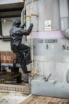
Component service intervals set the spare-parts plan for chemical dosing systems. Diaphragms fail first under chemical attack or fatigue; seals and O-rings control leaks; check valves set suction and discharge integrity; control panels fail when moisture or corrosion reaches the electronics. Treat the table below as the baseline, then shorten intervals when you dose abrasive slurry, strong oxidants, or outdoor UV-exposed tubing.
| Component | Inspection Interval | Replacement Interval | Failure Indicators | Notes |
|---|---|---|---|---|
| Diaphragm | Every 6 months | 12–18 months (depending on chemical aggressiveness and operating hours) | Cracks, thinning, bulging, stiffness, loss of flexibility, discoloration, chemical staining | Crucial for pump sealing and fluid displacement. Note any changes in stroke volume during calibration. |
| Seals and O-rings | Annually | Annually or per manufacturer’s chemical compatibility chart (whichever comes first) | Drying, cracking, hardening, visible wear, leaks, loss of elasticity | Essential for preventing chemical leaks and maintaining pump integrity. Ensure correct material selection for the specific chemical. |
| Solenoid Coils (if applicable) | Quarterly | As needed | Resistance deviation >10% from nominal, overheating, audible clicking failure, no response to electrical signal | Check resistance with a multimeter at room temperature. Monitor for excessive heat during operation. |
| Control Panel / Electronics | Monthly | As needed | Corrosion, loose connections, damaged wiring, indicator light failure, IP rating compromise, signs of water ingress, erratic behavior | Verify waterproof rating (IP65 minimum) and clean ventilation filters. Inspect for signs of overheating or electrical arcing. |
| Check Valves (Suction/Discharge) | Every 6 months | As needed | Clogging, wear on seating surfaces, stiffness, leakage, reduced flow rate, inconsistent dosing | Ensure proper sealing and flow direction. Disassemble and clean regularly, especially if dosing solids or viscous fluids. |
| Water-Powered Dosing Pumps | Quarterly | As needed | Reduced flow rate, inconsistent dosing, internal leaks, failure to draw chemical | Requires upstream pressure ≥ 3 bar for operation; rely on flow-induced pressure differentials. Inspect the water inlet filter for clogging. |
| Foot Valve / Strainer | Monthly | As needed | Clogging, damage to screen, loss of prime | Crucial for preventing debris from entering the pump. Clean as needed, especially if the source water is prone to sediment. |
Troubleshooting Common Dosing System Issues
Troubleshooting starts at the simplest cause before you open a pump head. Confirm tank level, closed valves, suction air leaks, and foot-valve submersion before blaming the diaphragm. A sticking backpressure valve at 5–7 bar can look like pump wear; a noisy 4–20 mA loop can look like inconsistent stroke. Keep lines flushed so crystallization does not fake a failed check valve.
| Symptom | Potential Root Cause | Corrective Action |
|---|---|---|
| No Chemical Delivery | Suction line blockage or air leak | Inspect suction line for obstructions; check for air leaks and tighten fittings. Ensure the foot valve is submerged and not blocked. |
| Air lock in pump head | Manually prime the pump or bleed air from the system using the bleed valve (if equipped). Ensure the pump is installed correctly to minimize air entrapment. | |
| Diaphragm rupture | Inspect and replace the diaphragm. Check for any sharp objects or debris in the pump chamber that may have caused damage. | |
| Check valve failure (stuck closed) | Disassemble, clean, and test check valves; replace if damaged. Ensure the valve orientation is correct. | |
| Chemical supply tank empty or valve closed | Verify chemical level in the tank and ensure the supply valve is open. | |
| Inconsistent Dosage / Pulsation | Pulsation dampener failure or air in the line | Check and repressurize or replace the dampener; bleed air from the system. Ensure the dampener is installed correctly with the correct pre-charge. |
| Control signal noise or instability | Ensure proper electrical grounding and shielding for control signals. Check for loose connections in the wiring harness. | |
| Stroke length or frequency not set correctly | Recalibrate pump settings. Verify that the control signals from the PLC are within the expected range. | |
| Worn pump internals (e.g., ball bearings in peristaltic pumps) | Inspect internal components for wear and replace as necessary. | |
| Leakage at Seal / Pump Head | Incorrect torque on seal housing or worn seals | Verify torque specifications (typically 8–10 Nm) and alignment; replace worn seals. Ensure the mating surfaces are clean and free of debris. |
| Cracked pump head or housing | Inspect for physical damage and replace the affected component. This can often be caused by freezing or over-pressurization. | |
| Improper gasket or O-ring installation | Ensure all seals and gaskets are correctly seated and lubricated before assembly. | |
| Pump Runs But No Flow | Check valves clogged or reversed | Disassemble, clean, and verify correct orientation of check valves. Ensure no debris is preventing proper seating. |
| Suction lift too high or flooded suction | Adjust pump placement or ensure proper suction conditions. The maximum suction lift is typically limited by pump design and atmospheric pressure. | |
| Discharge line blockage | Inspect and clear any blockages in the discharge piping. Check for kinks in flexible tubing. | |
| Loss of prime | Re-prime the pump and ensure all connections are airtight. | |
| PLC Alarm on Low Dose Confirmation (4-20 mA feedback) | Faulty feedback loop or sensor | Test the integrity of the 4–20 mA signal from the pump controller or flow meter. Check wiring and connections to the PLC. |
| Actual flow rate significantly lower than setpoint | Refer to "Inconsistent Dosage" or "No Chemical Delivery" sections. Perform a manual flow rate test to confirm the pump's output. | |
| Incorrect scaling of the 4-20 mA signal in the PLC | Verify the scaling parameters within the PLC program match the pump's output range. |
Selection Checklist and Next Step
Use this checklist before you lock intervals into the CMMS:
- Confirm LOTO covers electrical and chemical isolation per OSHA 29 CFR 1910.147.
- Match diaphragm, seal, and tubing materials to the dosed chemical and temperature.
- Set calibration tolerance at ≤ ±2% at normal operating pressure and temperature.
- Specify backpressure (typically 5–7 bar test range) and anti-siphon valves.
- Plan diaphragm inspection every 6 months and seal service annually or every 2,000 h.
- Require 4–20 mA dose confirmation if permit limits are tight.
- Stock wet-end kits sized for 4–12 month electronic-diaphragm duty where applicable.
Who this is for: plant engineers and EPC contractors running industrial or municipal dosing skids who need a repeatable service protocol. Who should look elsewhere: labs needing analytical method development, or sites seeking only bulk chemical procurement without equipment service. If you are sizing a new PLC-controlled package, review the PLC-controlled automatic chemical dosing system and request a quote with your duty data so stroke range, materials, and feedback loops match the process.
Frequently Asked Questions
How often should a chemical dosing pump be serviced?
A full service with diaphragm and seal checks should run every 6 months, with weekly visual leak checks in between. Corrosive or abrasive duties, continuous outdoor UV exposure, or high stroke counts often justify a quarterly wet-end review. Always compare your interval against the manufacturer schedule and shorten it when calibration drift exceeds ≤ ±2% between planned services.
What causes diaphragm failure in dosing pumps?
Diaphragm failure usually comes from chemical incompatibility, dry running, excess backpressure, abrasive media, or fatigue beyond about 2,000 operating hours. Overtightening the retaining hardware or running outside the design temperature range also shortens life. Catch cracks, thinning, bulging, or hardening at the 6-month inspection before a rupture dumps chemical into the drive.
Can parts of dosing maintenance be automated?
Yes. PLC-controlled skids can log stroke count, temperature, and pressure trends and alarm when 4–20 mA feedback drifts from setpoint. Flow meters close the loop so operators see under-dose before effluent leaves the plant. Automation does not replace LOTO, flush, or physical diaphragm inspection; it only flags when to open the head.
What tools are needed for dosing system maintenance?
Essential tools are a calibrated torque wrench (seal housings often land near 8–10 Nm), a calibration cylinder, a multimeter or loop calibrator, and chemical-resistant PPE. Add wrenches, screwdrivers, brushes, leak-detection fluid, and a flashlight for valve and tubing work. Keep the OEM compatibility chart at the bench so Viton, PTFE, or other seal swaps stay correct.
Is remote monitoring available for dosing systems?
Yes. Many PLC dosing packages support SCADA so operators track dose rate, alarms, and feedback from a control room or remote link. That layout suits multi-point plants and unmanned booster sites. Pair remote alarms with on-site calibration and wet-end service so the data stream matches real delivered volume.