
What Are Constructed Wetland Design Parameters?
Constructed wetland design parameters are the engineered inputs — hydraulic loading rate (HLR, typically 20–500 mm/d depending on type), hydraulic retention time (HRT, 2–14 days), water depth (20–80 cm), BOD area loading (≤110 kg/ha/d for FWS, up to 20 g BOD/m²·d for HF), media grain size, liner specification, and emergent vegetation density — that together govern treatment performance in a planted, lined reactor. In 2026 these parameters are set using two sizing philosophies consolidated by Vymazal in Water (2010): volume-based sizing driven by HRT (m³) and area-based sizing driven by pollutant load per unit bed area (m² per kg BOD/d). The UK Constructed Wetland Association (CWA) database now tracks more than 1,200 operational systems, the first full FWS CW was built in the Netherlands in 1967, and HF systems trace to Käthe Seidel's work in 1950s Germany (Vymazal, Water 2010; Cooper, Springer 2008).
The 2026 context is convergence on polishing roles. Tightening effluent limits — EU UWWTD 91/271/EEC, China GB 18918-2002 Class 1A, US EPA NPDES — are pushing CWs behind MBR or DAF units rather than as standalone primary treatment, especially for industrial streams where hydraulic and contaminant variability overwhelm a soil-based reactor. Engineers in 2026 most often size a CW to polish MBR permeate (typically <1 μm filtered, COD <50 mg/L, NH₃-N <5 mg/L) rather than to handle raw sewage or trade effluent alone.
Three CW Types and How Parameters Differ
CWs fall into three hydrologic families that determine the parameter ranges an engineer can use. Vymazal (2010) classifies them by vegetation (emergent, submerged, floating-leaved, free-floating), hydrology (free water surface, subsurface flow), and flow direction within subsurface systems (horizontal or vertical). Selecting the family is a prerequisite to reading any number off a parameter table.
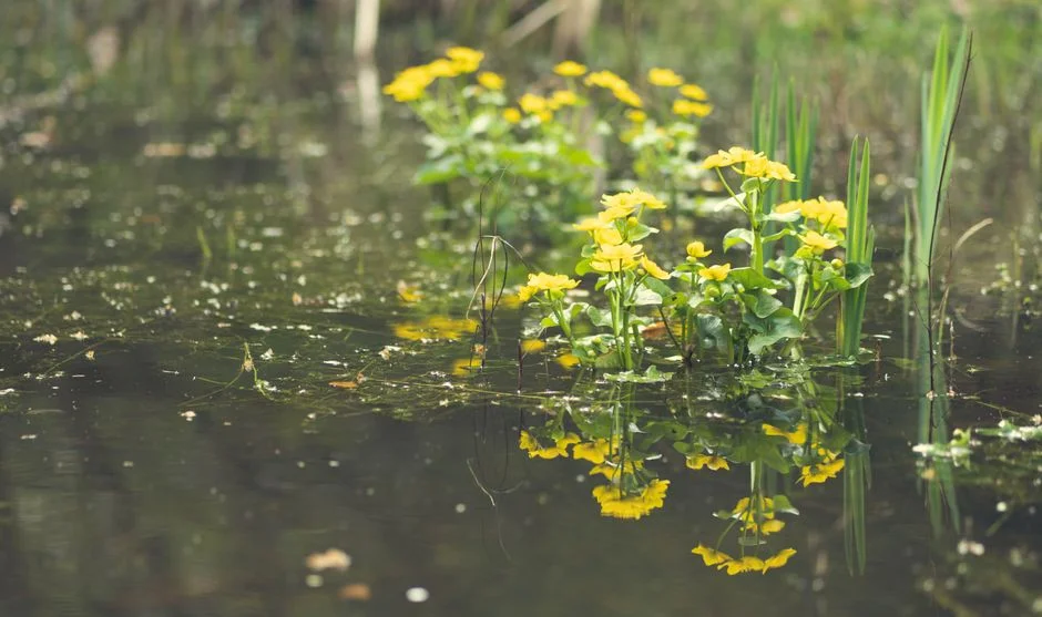
- Free Water Surface (FWS): a shallow, lined basin with 20–30 cm of rooting soil over clay or HDPE, 20–40 cm of standing water, emergent macrophytes. Dominant in North America and Australia; lowest capital cost but largest land footprint and exposed water surface (Vymazal, Water 2010).
- Horizontal Subsurface Flow (HF): a gravel/rock bed sealed with an impermeable liner, planted with reeds, wastewater flowing horizontally below the surface. Developed by Käthe Seidel in 1950s Germany using coarse media as the rooting medium. Better for BOD and denitrification, no exposed water, fewer mosquito/odor issues than FWS.
- Vertical Subsurface Flow (VF): wastewater percolates downward through unsaturated graded media; beds are dosed intermittently by pump, which creates a higher O&M burden but supplies the oxygen needed for nitrification. Seidel originally used VF beds to oxygenate anaerobic septic tank effluents (Vymazal, Water 2010).
- Hybrid VF+HF systems: staged configurations — typically VF → HF → HF (polishing) — built since the 1980s in France and the UK specifically for nitrogen removal, where the VF stage nitrifies and the downstream HF stage denitrifies (Vymazal, Water 2010).
| Feature | FWS | HF Subsurface | VF Subsurface | Hybrid VF+HF |
|---|---|---|---|---|
| Water surface | Exposed | Buried | Buried | Buried |
| Dominant region | North America, Australia | Europe (1980s–1990s) | Europe, UK | France, UK, DE |
| Best at | BOD, TSS, polishing | BOD, denitrification | Nitrification, BOD | Full BOD + N |
| Typical depth | 20–40 cm water | 60–80 cm media | 50–80 cm media | 50–80 cm each stage |
| Dosing | Continuous | Continuous | Intermittent (pumped) | Intermittent + continuous |
Master Parameter Table: HLR, HRT, Depth, and BOD Loading
The table below consolidates the Vymazal (2010) ranges and the CWA database scope into a single artifact that drops directly into a design basis memorandum. Values are typical engineering ranges, not guarantees; conservative design picks the lower bound for industrial polishing duty.
| Parameter | FWS | HF Subsurface | VF Subsurface | Hybrid VF+HF |
|---|---|---|---|---|
| Water depth | 20–40 cm | 60–80 cm (saturated) | 50–80 cm (unsaturated) | 50–80 cm each stage |
| Media | Fine soil/sand over clay | Coarse gravel 5–20 mm | Graded sand/gravel, 0.2–0.8 mm top layer | Per stage, VF over HF |
| HLR (mm/d) | 20–60 | 20–80 | 40–80 (intermittent) | 30–60 per stage |
| HRT (days) | 5–14 | 2–7 | 1–3 per dosing cycle | 4–10 total |
| BOD area loading | ≤110 kg/ha/d (typ. 50–80) | 5–20 g BOD/m²·d | 20–40 g BOD/m²·d | Use lower-bound HF |
| Vegetation density | 4–6 plants/m² | 4–6 plants/m² | 4–6 plants/m² | 4–6 plants/m² per stage |
| Plant uptake fraction | <10% of inflow N/P | <10% of inflow N/P | <10% of inflow N/P | <10% of inflow N/P |
| Liner | HDPE 1.0–1.5 mm or GCL if groundwater protection required | HDPE 1.0–1.5 mm mandatory | HDPE 1.0–1.5 mm mandatory | HDPE 1.0–1.5 mm mandatory |
| Typical vegetation | Phragmites, Typha, Scirpus | Phragmites australis dominant | Phragmites, Typha | Phragmites all stages |
Two facts from the table need to be foregrounded because they shape sizing. First, plant uptake is small: Vymazal (2010) reports that the amount sequestered in aboveground biomass "does not exceed 10% of the inflow nutrient load" in any CW type — meaning most removal is microbial and substrate-mediated, not plant-harvest-mediated. Second, Vymazal (2010) warns explicitly that "more complex models do not necessarily bring more precise design parameters" — the area- and volume-based methods in the next section are the engineering standard precisely because they match the available data.
Sizing a Constructed Wetland: Worked Calculation
The two sizing methods from Vymazal (2010) translate the parameter table into a defensible area and volume. The worked example below uses a 100 m³/d industrial polishing stream at 300 mg/L BOD, targeting ≤30 mg/L BOD and ≤5 mg/L NH₃-N — typical reuse or discharge numbers in 2026.
- Fix influent and target. Q = 100 m³/d, BOD = 300 mg/L, NH₃-N = 25 mg/L, target BOD ≤30 mg/L, NH₃-N ≤5 mg/L. Daily BOD load = 100 × 0.300 = 30 kg BOD/d.
- Pick CW type. NH₃-N is the design driver → select HF or hybrid VF+HF, not FWS. Use HF at conservative 10 g BOD/m²·d for industrial polishing.
- Area-based sizing. Required bed area = 30 kg BOD/d ÷ 0.010 kg BOD/m²·d = 3,000 m². (At the optimistic 20 g BOD/m²·d upper bound the area falls to 1,500 m².)
- Volume/HRT check. At 7-day HRT, required volume = 100 × 7 = 700 m³. Verify against bed area × depth: 3,000 m² × 0.7 m = 2,100 m³, which exceeds 700 m³ by 3× — the bed is HRT-rich, which is the safe direction for an industrial stream with diurnal flow swings.
- Apply safety factor. Add 20–30% to bed area for winter temperature derating, partial clogging, and uneven distribution — 3,000 m² × 1.25 = 3,750 m² final HF bed, split into 2 parallel cells of 1,875 m² for operational redundancy.
For an MBR-effluent polishing case (BOD <30 mg/L already), the same calculation at 10 g BOD/m²·d with a 30 kg/d load becomes tractable: 3,000 m² for 100 m³/d, or 30 m² per m³/d, which is on the high end because BOD loading is high relative to a typical reuse stream. A 50 mg/L polishing case at 5 kg BOD/d against 10 g BOD/m²·d needs 500 m², or 5 m² per m³/d — the typical 2–5 m²/m³/d figure cited in design handbooks.
Where a Constructed Wetland Fits in a 2026 Industrial Treatment Train
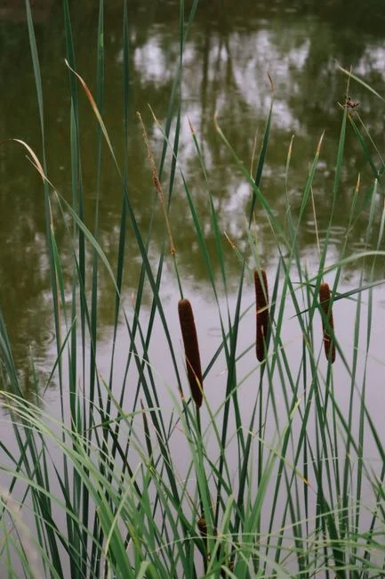
A CW is a biological reactor with limited hydraulic buffer — it is not an oil/grease or TSS remover. The 2026 consensus for industrial streams is to treat the CW as a polishing stage behind mechanical and biological units, not as a standalone train. The CWA database confirms that the majority of UK CW sites treat domestic sewage as tertiary polishing, with smaller subsets for mine water, landfill leachate, and industrial effluents (Cooper, Springer 2008).
A representative 2026 train for electroplating, textile, or food-processing effluent is: equalization → DAF pre-treatment (oil/grease, TSS, partial COD) → A/O or AAO biological (an AAO biological train is common for nitrogen) → MBR membrane bioreactor (delivers <1 μm filtered permeate at COD <50 mg/L) → VF/HF polishing wetland for residual organics, color, and trace metals. The VF stage handles nitrification, the HF stage handles denitrification, and the entire wetland sits inside a lined cell with HDPE 1.0–1.5 mm. For trade effluents with high oil or fiber content, a DAF pre-treatment unit upstream is non-negotiable — without it, the wetland inlet media clogs within months, not years.
For municipal/domestic sewage the train is shorter: primary clarification → activated sludge or oxidation ditch → VF/HF polishing. The CWA database scope confirms this is the dominant UK deployment pattern (Cooper, Springer 2008).
Industrial Influent Adjustments and Common Pitfalls
The academic literature on CWs is dominated by municipal sewage; industrial applications are where field projects actually fail. The adjustments below cover the four influent classes most often seen in 2026 RFQs.
| Influent class | Pre-CW treatment required | Design adjustment | Common failure mode |
|---|---|---|---|
| Electroplating | pH adjust, precipitation, sand filtration for heavy metals | Confirm metal removal to <1 mg/L before bed; reduce design BOD loading by 30% | Metal toxicity to bed microbes; documented in polishing studies (per theses.fr, 2013) |
| Textile | Anaerobic + ozonation for color/sulfate | Use VF first stage, dose intermittently, expect color reduction 50–70% | Color breakthrough and sulfate-driven H₂S in HF beds |
| Landfill leachate | Ammonia stripping or SBR upstream | Size for NH₃-N 200–500 mg/L, target 70% removal; multi-stage VF/HF | Free ammonia inhibition at high pH |
| Municipal/domestic | Primary clarification | Standard FWS or HF sizing per CWA database (Cooper, 2008) | Hydraulic overload during wet weather |
Three field failures appear repeatedly and are worth flagging on every P&ID. (1) Hydraulic overload — exceeding the design HLR by 30% drops COD removal from ~80% to under 50% in HF beds, the most common field failure mode. (2) Media clogging in VF beds — prescribe dosing rest cycles of 15 min on / 30 min off, with graded media (coarse at bottom, 0.2–0.8 mm sand on top) to keep infiltration uniform. (3) Cold-climate derating — at influent temperatures below 10 °C, nitrification efficiency can halve; in northern deployments, either oversize the VF stage by 30% or install a greenhouse cover to maintain bed temperature above 5 °C year-round.
Frequently Asked Questions
What is the typical hydraulic loading rate for a constructed wetland?
Per Vymazal (2010), typical HLR ranges are FWS 20–60 mm/d, HF 20–80 mm/d, and VF 40–80 mm/d with intermittent pumped dosing. For MBR-effluent polishing, run the lower third of the range (20–30 mm/d) to keep HRT above 5 days.
What BOD area loading should I use to size an HF bed?
The published range is 5–20 g BOD/m²·d. For industrial polishing, design conservatively at 10 g BOD/m²·d; for domestic secondary treatment, 15–20 g BOD/m²·d is acceptable. These align with the Vymazal (2010) range and the CWA database population (Cooper, Springer 2008).
How much land does a constructed wetland need per m³/d of flow?
Roughly 5–15 m² per m³/d for secondary treatment of domestic sewage, and 2–5 m² per m³/d when polishing MBR effluent (BOD already <30 mg/L). Industrial streams with high BOD (>300 mg/L) push land requirement to 20–30 m² per m³/d, which is why a CW alone is rarely economic for industrial duty.
Can a constructed wetland meet EPA NPDES discharge limits on its own?
Rarely for industrial streams. CWs are typically used as a polishing step behind an MBR, DAF, or activated-sludge train. For domestic sewage, FWS or HF systems can meet secondary limits but rarely achieve the ammonia and total nitrogen limits in EU UWWTD 91/271/EEC or strict NPDES permits without a hybrid VF+HF configuration and biological upstream treatment.
What is the difference between VF and HF constructed wetlands?
VF (vertical subsurface flow) percolates wastewater downward through unsaturated media and supports strong nitrification, but it needs pumped intermittent dosing and has higher O&M burden. HF (horizontal subsurface flow) flows horizontally through saturated gravel, is better for BOD removal and denitrification, and runs continuously without dosing pumps. Hybrid systems pair the two for full BOD + N removal (Vymazal, Water 2010).