

Why Tank Bottom Water Is Not a Standard MBBR Feed
Tank bottom water — the aqueous layer drained from crude oil, diesel, slop-oil, or chemical storage tanks — arrives at the treatment train as a stable oil/water/sediment emulsion rather than standard industrial wastewater. Typical composition in refinery and terminal tank farm operations runs free oil at 200–2,000 mg/L, total suspended solids (TSS) at 500–5,000 mg/L, and COD at 800–5,000 mg/L, with intermittent sulfides, phenols, and TDS slugs when brine bottoms are co-mingled. The stream also drains batch-wise: a tank emptying can deliver 3–5× the daily average flow for two to three hours, which is why off-the-shelf MBBR sizing built on municipal 24-hour averages underperforms here.
Biofilm carriers tolerate moderate organics, but they cannot tolerate an oil-wetted surface. A 2023 review in Frontiers in Microbiology (doi 10.3389/fmicb.2023.1166907) lists the moving bed biofilm reactor among the biological options for oilfield produced water, and the same study places MBBR strictly downstream of oil/water separation. When tank bottom water reaches the reactor with free oil above 50 mg/L, hydrocarbons coat the HDPE carrier and the protected biofilm area drops by 30–60% within four to six weeks. The designer then has a 6–12 hr HRT reactor that is effectively operating at the hydraulic retention time of a 3–5 hr unit — and discharge COD drifts above the permit band.
The 7-Step MBBR Sizing Protocol for Tank Bottom Water
A defensible moving bed biofilm reactor design for tank bottom water follows a fixed sequence to prevent the chronic under-performance seen at retrofitted tank farms.
- Characterize the stream. Pull 24-hour composite samples for COD, BOD₅, TSS, free and emulsified oil (HEM method, EPA 1664), sulfides, salinity, pH, and temperature. Confirm the peak 2-hour flow from tank-draining logs, not the daily average. If the plant runs multiple product tanks, sample each one — diesel bottoms and slop-oil bottoms behave differently.
- Hold the pre-treatment gate. Specify a dissolved air flotation system or a corrugated-plate interceptor (CPI) upstream of the MBBR. Target free oil to <50 mg/L and TSS to <100 mg/L entering the reactor. DAF typically operates at a hydraulic loading of 5–15 m³/m²·h with an air-to-solids (A/S) ratio of 0.02–0.05; this removes emulsified oil down to the 20–40 mg/L band needed to keep carriers clean. For sizing a DAF for oily industrial streams, the envelope is narrow enough that conservative hydraulic loading is cheaper than replacing fouled media.
- Pick the HRT. Use 6–12 hours for tank bottom water. The IJSR river-water review (doi 10.21275/art20179091) sets the broader MBBR envelope at 4–15 hours, but tank bottom water's shock-loading profile — and its tendency to push COD spikes above 3,000 mg/L during tank draining — calls for the upper half of that range. Stay at 6 hr only when influent COD is consistently below 1,000 mg/L.
- Set media fill. Specify 30–50% of effective reactor volume as HDPE Kaldnes K1 or K3 carriers. The Tanjungpura Kaldnes K1 study (doi 10.26418/jtllb.v7i1.31882) demonstrated treatment effectiveness at 20% fill on laundry wastewater, but tank bottom water's higher organic load and emulsion residuals benefit from the higher end. Below 30%, the reactor loses too much protected surface area; above 50%, mixing fails and dead zones form at the bottom.
- Compute reactor volume. V_reactor = Q × HRT, then divide by a fill factor of 0.4–0.6 to convert working volume to empty tank volume. Add 20% for swing zones, aeration dead volume, and baffle clearance. For a peak flow of 25 m³/h at 8 hr HRT, the working volume is 200 m³; the empty tank is closer to 500 m³ once fill and head-space are accounted for.
- Size aeration. Hold dissolved oxygen at ≥4 mg/L across 20–25 °C operation. Calculate standard oxygen transfer rate (SOTR) using a coarse-bubble grid transfer efficiency of 12–18% — fine-bubble diffusers plug fast on oily residuals even after DAF. Apply a 1.3× turndown factor for shock loads. A coarse-bubble grid at 15% efficiency typically needs 6–8 Nm³ air per kg BOD removed for this waste class.
- Apply a toxicity safeguard. Hold pH at 6.5–8.5, sulfide below 2 mg/L, and free ammonia below 5 mg/L. If chlorides exceed 8,000 mg/L, switch to salinity-tolerant media (high-density PE with biofilm-promoting surface texture) and step the HRT up 30%. Continuous online ORP and sulfide monitoring with an emergency chlorination or peroxide interlock protects the biomass from slug events common when brine bottoms or desalter wash water enter the same sewer.
Key Design Parameters at a Glance
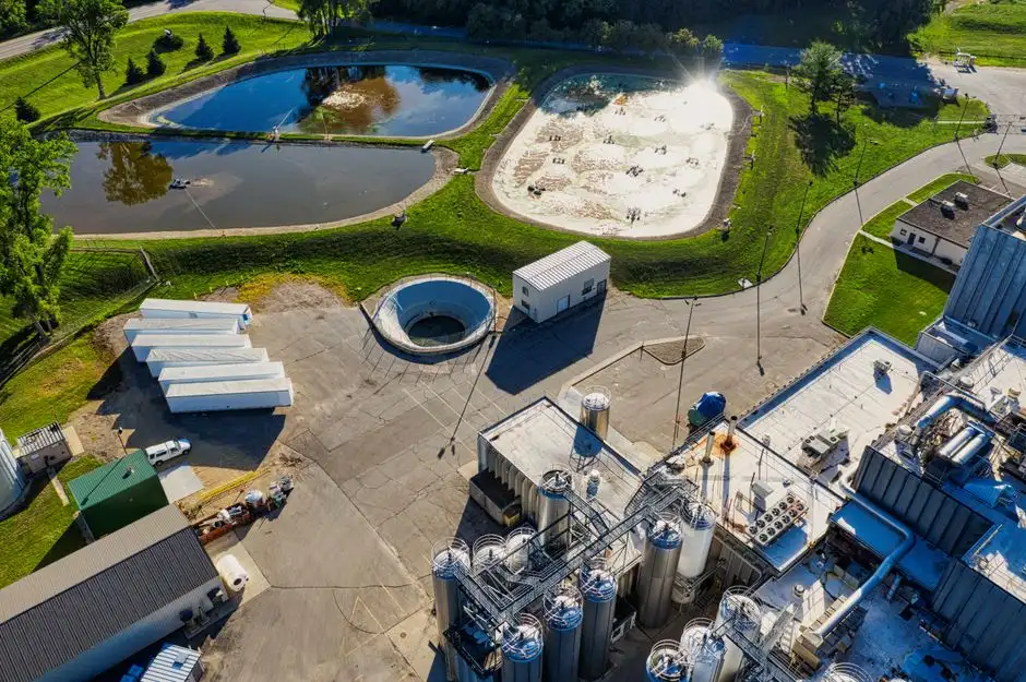
The table below consolidates the eight parameters that govern every MBBR datasheet for tank bottom water, serving as a reference for HAZOP and design-review packs.
| Parameter | Typical Range for Tank Bottom Water | Source / Justification |
|---|---|---|
| HRT | 6–12 hr (8 hr typical) | IJSR 2017 review (doi 10.21275/art20179091); tightened for shock loading |
| Media fill (HDPE K1/K3) | 30–50% of effective volume | Tanjungpura Kaldnes K1 study (doi 10.26418/jtllb.v7i1.31882); raised for higher organic/emulsion load |
| F/M ratio | 0.2–0.5 kg BOD/kg MLVSS·d | Standard MBBR design envelope; lower end for high-strength oily feed |
| Dissolved oxygen | ≥4 mg/L at 20–25 °C | Aerobic heterotrophic threshold; coarse-bubble grid at 12–18% SOTE |
| Temperature | 20–25 °C optimal; degrade below 12 °C | Biofilm kinetics; double HRT or shelter media in cold climates |
| pH | 6.5–8.5 | Nitrifier/integrated biofilm operating window |
| Oil-in tolerance | <50 mg/L free, <20 mg/L emulsified | Frontiers in Microbiology 2023 (doi 10.3389/fmicb.2023.1166907) — MBBR strictly downstream of oil/water separation |
| Carrier specific surface area | 500 m²/m³ (K1, 40% fill) | Manufacturer data; reduced 30–60% by oil coating if pre-treatment gate is skipped |
Worked Sizing Example: 10 m³/h Tank Bottom Stream
Designing for a 10 m³/h flow requires calculating for the specific load profile of tank bottom water.
Step 1 — Characterize: The COD/BOD₅ ratio of 0.4 confirms a slowly biodegradable, emulsion-rich stream typical of crude tank bottoms. Step 2 — Pre-treatment: route through a dissolved air flotation system at 8 m³/m²·h hydraulic loading and A/S = 0.03. After DAF, free oil drops to ~30 mg/L and TSS to ~80 mg/L — both inside the MBBR tolerance band. Step 3 — Pick HRT = 8 h, the midpoint of the 6–12 hr envelope appropriate for ~1,500 mg/L COD influent. Step 4 — Reactor working volume: V = 10 × 8 = 80 m³. Apply a 0.5 fill factor for the 40% media fill plus 20% head-space allowance, giving an empty tank of approximately 200 m³. Step 5 — Biofilm surface area: 40% HDPE K1 fill provides roughly 500 m² of protected area per m³ of working volume, for ~32,000 m² total — more than enough for the 6 kg BOD/h loading at F/M ≈ 0.3. Step 6 — Aeration: target SOTR ≈ 16 kg O₂/h to hold 4 mg/L DO with 15% transfer efficiency, equating to about 110 Nm³/h of blower air through a coarse-bubble grid. The 1.3× turndown factor brings design airflow to 140 Nm³/h. Step 7 — Toxicity safeguard: hold pH at 7.0–8.0, sulfide below 2 mg/L via continuous ORP, and route the MBBR effluent through an MBR membrane bioreactor polishing stage if discharge targets demand TSS below 10 mg/L. Expected performance on this stream: effluent COD <150 mg/L, BOD₅ <30 mg/L when influent loads stay within 1.3× of design.
Common MBBR Sizing Mistakes on Tank Bottom Water

Five errors appear in nearly every retrofit that fails its first performance test.
Mistake 1 — Using average daily flow instead of peak 2-hour flow. Tank draining is batch. A 50 m³/day average stream can deliver 250 m³ between 09:00 and 11:00 when a crude tank is dropped. Size the reactor for the peak, or install an equalization basin upstream of the MBBR.
Mistake 2 — Skipping the DAF. When free oil exceeds 50 mg/L entering the reactor, HDPE carriers coat with hydrocarbon film and lose 30–60% of specific surface area in four to six weeks. The fix is rarely more media; it is upstream oil removal.
Mistake 3 — Undersizing aeration. Tank bottom water's BOD/COD ratio below 0.4 means slow biodegradation and extended endogenous decay. The reactor demands high DO for longer residence, not the short bursts that municipal designs assume. Coarse-bubble grids stay cleaner than fine-bubble on this feed class.
Mistake 4 — Ignoring cold-weather performance. Below 12 °C, biofilm kinetics slow enough that the same HRT delivers 30–40% less BOD removal. Either double the HRT, insulate the tank, or add an enclosure over the reactor deck.
Mistake 5 — Forgetting sulfide and phenol slugs. When desalter wash water or chemical-tank bottoms enter the same sewer, sulfides spike above 5 mg/L and shut down nitrification. Continuous online ORP and sulfide monitoring with an emergency chlorination or H₂O₂ interlock protects the biomass and keeps the plant inside its discharge permit.
Frequently Asked Questions
What HRT should I use for an MBBR treating tank bottom water?
For tank bottom water with influent COD between 800 and 5,000 mg/L, design the MBBR for an HRT of 6–12 hours, with 8 hours as the typical midpoint. The IJSR 2017 review (doi 10.21275/art20179091) sets the broader MBBR envelope at 4–15 hours, but tank bottom water's shock-loading and emulsion residuals push the design toward the upper half of that range. Below 6 hours, expect incomplete BOD removal during tank-draining peaks.
Can an MBBR handle free oil, or do I need a DAF first?
You need a DAF or CPI upstream
Frequently Asked Questions
How do you size an MBBR for tank bottom water?
Sizing an MBBR for tank bottom water requires calculating the organic load based on the specific Chemical Oxygen Demand (COD) and petroleum hydrocarbon concentration of the influent. Engineers must determine the required Surface Area Loading Rate (SALR), typically ranging from 5 to 20 g sCOD/m²/day depending on the biodegradability of the specific oil fractions present.
The total required surface area is calculated by dividing the daily organic mass load by the design SALR. Once the total surface area is defined, the volume of the reactor is determined by selecting a carrier media with a known protected surface area (typically 500 to 800 m²/m³) and applying the design fill fraction.
What is the right HRT for an MBBR treating oily wastewater?
The Hydraulic Retention Time (HRT) for oily wastewater treatment generally ranges from 6 to 24 hours, depending on the complexity of the hydrocarbons and the downstream discharge requirements. Higher molecular weight compounds or emulsified oils require the longer end of this range to allow for sufficient enzymatic hydrolysis and microbial degradation.
Because tank bottom water often contains high concentrations of recalcitrant organics, an HRT of at least 12 hours is recommended to ensure stable microbial kinetics and prevent biomass washout during fluctuations in influent composition.
Do you need a DAF before an MBBR for tank bottom water?
Yes, a Dissolved Air Flotation (DAF) unit is strongly recommended as a pretreatment step for tank bottom water. MBBR processes are highly sensitive to free-phase oils and grease, which can coat the biofilm carriers, block oxygen transfer, and inhibit microbial attachment.
Pretreatment via DAF should target an Oil and Grease (O&G) concentration of less than 50 mg/L before the water enters the MBBR. Failure to remove bulk oil typically results in carrier blinding, significantly reducing the effective surface area and causing system failure.
What media fill percentage should I use for an MBBR on oily streams?
For oily wastewater streams, a media fill percentage between 35% and 50% is standard. While some systems can technically operate at up to 65%, keeping the fill fraction at or below 50% is critical in oily applications to maintain adequate mixing and prevent the media from clumping due to the sticky nature of residual hydrocarbons.
Lower fill percentages also reduce the risk of head loss and allow for more efficient aeration, which is vital for maintaining the high dissolved oxygen levels required to metabolize complex petroleum fractions.
How much dissolved oxygen does an MBBR need for tank bottom water?
The MBBR must maintain a bulk Dissolved Oxygen (DO) concentration of 4.0 to 6.0 mg/L to effectively treat tank bottom water. Unlike standard municipal wastewater treatment, which may operate at 2.0 mg/L, the high oxygen demand of hydrocarbon degradation requires elevated DO levels to ensure oxygen penetrates the deeper layers of the biofilm.
Maintaining these levels is essential for the aerobic bacteria to break down complex long-chain alkanes and aromatic compounds. If DO levels drop below 3.0 mg/L, the system may experience incomplete oxidation, leading to odor issues and the production of metabolic byproducts.
