Why Two-Stage Chemical Precipitation Outperforms Single-Stage for Fluoride Removal
Two-stage chemical precipitation achieves 99.5%+ fluoride removal from industrial wastewater, reducing concentrations from 5,000 mg/L to below 10 mg/L—meeting EPA and China GB 8978-1996 discharge limits. This process combines calcium chloride (CaCl₂) and magnesium salts in sequential pH-adjusted stages (pH 8.5–11.0), optimizing reaction kinetics for high-efficiency CaF₂ precipitation while minimizing chemical sludge volume. Systems like Zhongsheng Environmental’s PLC-controlled chemical dosing skids for two-stage fluoride precipitation handle flows up to 300 m³/h with PLC-controlled precision.
A semiconductor fabrication plant in East Asia recently faced regulatory pressure when its existing single-stage treatment system failed to meet a new 10 mg/L discharge limit. Despite increasing calcium dosing to 3.0× stoichiometric ratios, the plant could not consistently drop fluoride below 25 mg/L. This plateau is a known limitation: single-stage systems typically reach a removal ceiling of 85–90% for influent concentrations exceeding 1,000 mg/L (per 2024 EPA Industrial Wastewater Guidelines). The kinetic limitations of calcium fluoride (CaF₂) precipitation, governed by a solubility product (Ksp) of 3.9 × 10⁻¹¹ at 25°C, mean that as fluoride concentration drops, the driving force for crystal growth diminishes, leaving residual ions in solution.
Two-stage systems overcome these limitations through controlled nucleation and sequential polishing. The first stage targets the bulk of the fluoride load using calcium chloride (CaCl₂) at a moderately alkaline pH (8.5–9.5), where the majority of CaF₂ precipitates into dense, fast-settling crystals. The second stage introduces magnesium salts (MgCl₂ or MgSO₄) at a higher pH (10.0–11.0). In this environment, the formation of magnesium hydroxide [Mg(OH)₂] flocs provides a high surface area for the adsorption of residual fluoride ions, pushing the final effluent concentration well below 10 mg/L. In the aforementioned semiconductor case, the transition to a two-stage configuration reduced fluoride from 5,000 mg/L to 8.4 mg/L, ensuring 100% compliance with local standards.
| Parameter | Single-Stage Precipitation | Two-Stage Chemical Precipitation |
|---|---|---|
| Maximum Removal Efficiency | 85–92% | 99.5–99.9% |
| Typical Effluent Fluoride | 15–30 mg/L | <10 mg/L (often <2 mg/L) |
| Chemical Consumption | High (due to over-dosing for polishing) | Optimized (stoichiometric precision) |
| Sludge Characteristics | High volume, lower density | Lower volume, high-density CaF₂ primary sludge |
| Process Stability | Sensitive to influent spikes | Highly resilient to load fluctuations |
Engineering Specs for Two-Stage Fluoride Precipitation: pH, Chemicals, and Reaction Kinetics
Engineering a high-performance fluoride removal system requires precise control over chemical stoichiometry and reaction residence times. Stage 1 focuses on the primary precipitation of calcium fluoride. To achieve optimal results, CaCl₂ is dosed at a 1.2–1.5× stoichiometric ratio relative to the influent fluoride (Ca²⁺:F⁻). Maintaining a pH range of 8.5–9.5 is critical; if the pH exceeds 10.0 in this stage, calcium carbonate may compete for calcium ions, increasing chemical waste. The reaction time for Stage 1 should be maintained between 15 and 30 minutes to allow for sufficient crystal nucleation (per 2025 Zhongsheng Environmental benchmarks).
Stage 2 serves as the polishing phase, utilizing magnesium salt dosing (MgCl₂ or MgSO₄) at a 0.8–1.0× stoichiometric ratio (Mg²⁺:F⁻). The pH must be elevated to 10.0–11.0 to facilitate the precipitation of Mg(OH)₂, which acts as a powerful adsorbent for residual fluoride. This stage requires a longer reaction time of 20–40 minutes due to the slower kinetics of adsorption compared to direct precipitation. For systems treating fluoride and TMAH recovery in semiconductor wastewater, maintaining these specific kinetics is vital to prevent interference from organic surfactants.
Sludge settleability is a primary indicator of system health. CaF₂ sludge from Stage 1 typically exhibits a Sludge Volume Index (SVI) of <80 mL/g, making it highly suitable for rapid clarification. Mg(OH)₂ sludge from Stage 2 is more flocculent, with an SVI <120 mL/g, necessitating the use of high-molecular-weight anionic polyacrylamide (PAM) as a coagulant aid. Temperature also plays a role: at temperatures below 15°C, reaction kinetics slow significantly, often requiring a 20% increase in residence time or the addition of heat to maintain removal efficiency.
Example Stoichiometric Calculation:
To treat an influent flow with 1,000 mg/L of fluoride (F⁻):
1. Molar concentration of F⁻ = 1,000 mg/L / 19 g/mol = 52.6 mmol/L.
2. Required Ca²⁺ at 1.5× ratio = (52.6 / 2) * 1.5 = 39.45 mmol/L.
3. CaCl₂ mass required = 39.45 mmol/L * 111 g/mol = 4.38 g of CaCl₂ per liter of wastewater.
| Engineering Parameter | Stage 1 (Calcium Stage) | Stage 2 (Magnesium Stage) |
|---|---|---|
| Primary Chemical | Calcium Chloride (CaCl₂) | Magnesium Chloride (MgCl₂) |
| Target pH Range | 8.5 – 9.5 | 10.0 – 11.0 |
| Stoichiometric Ratio | 1.2 – 1.5× (Ca:F) | 0.8 – 1.0× (Mg:F) |
| Reaction Time (HRT) | 15 – 30 Minutes | 20 – 40 Minutes |
| Coagulant Aid | Anionic PAM (1–3 mg/L) | Anionic PAM (2–5 mg/L) |
System Design: Equipment, Automation, and Flow Diagrams for Industrial Applications
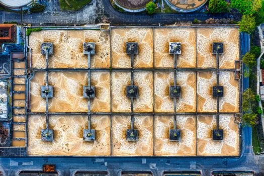
The physical architecture of a two-stage system must integrate chemical dosing, reaction, and solid-liquid separation into a seamless, automated loop. The process begins in an equalization tank, sized for 2–4 hours of hydraulic retention time (HRT) to dampen fluctuations in fluoride concentration and acidity. From there, wastewater enters the Stage 1 pH adjustment and reaction tanks, followed by the Stage 2 tanks. Consistent performance in semiconductor fabs, which often run 24/7, requires lamella clarifiers for fluoride sludge separation that can handle high solids loading without carryover.
Automation is the cornerstone of "zero-risk" compliance. Modern systems utilize PLC-controlled dosing pumps with ±2% accuracy, slaved to real-time pH and flow sensors. In high-stakes environments like zero-liquid discharge (ZLD) systems for fluoride-laden etching wastewater, redundancy is non-negotiable. Dual-head dosing pumps and redundant pH probes ensure that a sensor failure does not lead to an out-of-compliance discharge event. The system flow generally follows this sequence: Equalization → Stage 1 Precipitation → Stage 2 Precipitation → Flocculation → Lamella Clarification → Effluent Monitoring → Sludge Thickening → Dewatering.
For sludge management, filter presses for dewatering CaF₂ and Mg(OH)₂ sludge are preferred over centrifuges because they produce a drier cake (35–45% solids), significantly reducing disposal costs. The integration of a turbidity meter at the clarifier overflow provides an immediate alert if flocculation is failing, allowing the PLC to automatically divert off-spec water back to the equalization tank for retreating.
Cost Breakdown: CapEx, OpEx, and ROI for Two-Stage Fluoride Treatment Systems
The financial justification for a two-stage system relies on the balance between higher initial capital expenditure (CapEx) and significantly lower operational risks and fines. For a system with a capacity of 100 m³/h, CapEx typically ranges from $120,000 to $250,000 ($1,200–$2,500/m³/h), depending on the level of automation and materials of construction (e.g., FRP vs. 316L Stainless Steel). While this is 30–50% higher than a single-stage system, the ability to meet stringent <10 mg/L limits avoids the potential for daily fines that can exceed $10,000 in strictly regulated zones.
Operational expenditure (OpEx) for two-stage treatment usually falls between $0.80 and $1.50 per cubic meter of treated water. Chemicals represent the largest share of this cost. Calcium chloride is relatively inexpensive at $200–$300 per ton, while magnesium chloride is a premium reagent at $400–$600 per ton. However, because Stage 2 only treats residual fluoride, the actual mass of magnesium required is low. Sludge disposal costs are also optimized; because the two-stage process produces a more compact, crystalline CaF₂ sludge in the first stage, the total volume of hazardous waste generated is often 20% lower than "over-dosed" single-stage systems.
| Cost Component | Estimated Cost (USD) | Percentage of OpEx |
|---|---|---|
| Chemicals (CaCl₂, MgCl₂, NaOH, PAM) | $0.30 – $0.60 / m³ | 40% |
| Sludge Disposal | $0.20 – $0.40 / m³ | 27% |
| Labor & Maintenance | $0.20 – $0.30 / m³ | 20% |
| Electricity | $0.10 – $0.20 / m³ | 13% |
| Total OpEx | $0.80 – $1.50 / m³ | 100% |
Return on investment (ROI) is typically realized within 18 to 36 months. This calculation includes the avoidance of environmental non-compliance penalties and the reduced labor costs associated with Zhongsheng Environmental’s automated dosing systems, which require 50% less operator intervention than manual chemical adjustment setups.
Compliance Standards and Discharge Limits: Global Regulations for Fluoride in Industrial Wastewater

Compliance managers must navigate a complex web of regional regulations that dictate the required efficiency of fluoride treatment systems. In China, the GB 8978-1996 standard remains the benchmark, setting fluoride limits at 10 mg/L for new semiconductor plants and 15 mg/L for existing chemical facilities. However, local "Blue Sky" initiatives in provinces like Jiangsu often enforce even stricter limits of 5–8 mg/L for facilities discharging into sensitive watersheds.
In the United States, the EPA's 40 CFR Part 415 (Inorganic Chemicals Manufacturing) generally sets fluoride limits at 30 mg/L for many industrial categories, but the 2025 updates have pushed semiconductor-specific guidelines toward 10 mg/L to match international best practices. The European Union’s Industrial Emissions Directive (2010/75/EU) follows a similar path, with Best Available Techniques (BAT) reference documents suggesting 5–15 mg/L depending on the industrial sector and the sensitivity of the receiving water body.
| Region/Standard | Fluoride Limit (mg/L) | Industry Focus |
|---|---|---|
| China GB 8978-1996 | 10 – 15 mg/L | Semiconductors & General Industry |
| US EPA 40 CFR 415 | 10 – 30 mg/L | Inorganic Chemicals & Electronics |
| EU Directive 2010/75/EU | 5 – 15 mg/L | Chemical & Metal Processing |
| Taiwan EPA Standard | 10 mg/L | High-Tech Fabs (e.g., TSMC) |
Documentation of compliance is as critical as the treatment itself. Regulators are increasingly moving from "grab samples" (single point-in-time tests) to 24-hour composite sampling. A two-stage system provides the stability needed to ensure that composite samples remain consistently below the limit, whereas single-stage systems often suffer from "spiking" during influent load changes, leading to failed composite tests even if most grab samples are passing.
Single-Stage vs. Two-Stage Chemical Precipitation: Which System Fits Your Fluoride Load?
The choice between single-stage and two-stage systems depends on three variables: influent concentration, discharge limits, and flow volume. For facilities like small metal finishing shops where fluoride concentrations are consistently below 1,000 mg/L and discharge limits are a lenient 20–30 mg/L, a single-stage system using CaCl₂ at pH 9.0 is often sufficient. These systems have a lower CapEx ($800–$1,500/m³/h) and a smaller footprint, making them ideal for space-constrained sites.
However, for semiconductor fabs, glass etching plants, or large-scale chemical producers where influent fluoride exceeds 1,000 mg/L and compliance limits are <10 mg/L, a two-stage system is the only reliable engineering choice. The decision matrix below provides a framework for selection. Before finalizing a system design, engineers should conduct a "jar test" to simulate the two-stage process. This involves dosing a 1L sample with CaCl₂ at pH 9.0, decanting the supernatant, and then dosing the remaining liquid with MgCl₂ at pH 10.5 to verify that the specific wastewater chemistry responds to the sequential treatment.
| Factor | Select Single-Stage If... | Select Two-Stage If... |
|---|---|---|
| Influent Fluoride | < 1,000 mg/L | > 1,000 mg/L |
| Required Effluent | > 15 mg/L | < 10 mg/L |
| Flow Variability | Low / Constant | High / Batch Discharges |
| Sludge Disposal Cost | Not a primary concern | Primary OpEx driver (needs reduction) |
| Regulatory Risk | Low (Non-sensitive area) | High (Strict EPA/GB enforcement) |
Frequently Asked Questions
What is the primary cause of failure in two-stage fluoride systems?
The most common failure point is poor pH control in the second stage. If the pH drops below 10.0, magnesium hydroxide will not form correctly, and the adsorption of residual fluoride will cease. Zhongsheng Environmental systems utilize high-sensitivity pH probes with automatic self-cleaning cycles to prevent this issue.
Can I upgrade my existing single-stage system to a two-stage system?
Yes. Most single-stage systems can be retrofitted by adding a secondary reaction tank and a magnesium dosing skid. However, the clarifier capacity must be evaluated to ensure it can handle the additional Mg(OH)₂ floc load without carryover.
How does the presence of phosphates affect fluoride precipitation?
Phosphates will compete with fluoride for calcium ions in Stage 1. If your wastewater contains high phosphate levels, the stoichiometric ratio of CaCl₂ must be increased to account for the formation of calcium phosphate [Ca₃(PO₄)₂]. Failure to adjust this ratio will result in incomplete fluoride removal.
Is the sludge from two-stage precipitation considered hazardous?
In most jurisdictions, CaF₂ sludge is classified as industrial waste rather than hazardous waste, provided it does not contain heavy metals. However, local regulations vary, and a TCLP (Toxicity Characteristic Leaching Procedure) test is recommended for proper classification.