
Primary Clarifier Troubleshooting Steps That Work
Primary clarifier troubleshooting focuses on floating sludge, short-circuiting, bottom scour, and drive failures that cut solids capture. Well-run primary clarifiers remove 50–70% of TSS and 25–40% of BOD before biological treatment under typical industrial loadings. A 10% drop in primary TSS removal can raise aeration energy use by about 15% at the basins.
According to EPA guidance for industrial wastewater facilities, those removal bands are the usual design expectation for settleable solids. Inadequate solids removal increases organic loading on secondary systems and raises the risk of sludge bulking, elevated effluent TSS, and permit violations. In food and beverage plants with high organic peaks, weak primary treatment can overload biology during production surges. Restored primary capture often cuts polymer use, aeration demand, and sludge handling enough to recover upgrade cost within two years.
Symptom 1: Floating Sludge in the Clarifier Tank
Floating sludge in a primary clarifier is most often caused by a septic sludge blanket. Anaerobic digestion forms methane and CO₂ that buoy solids to the surface. Confirm withdrawal frequency first: sludge should not remain in the tank for more than two hours, or septicity and gas formation begin. Use a portable H₂S meter at the surface—readings above 1 ppm confirm active anaerobic activity in the blanket.
Increase sludge pump-out frequency and inspect scrapers for stalls or failed flights. Temporary chlorine dosing at 2–5 mg/L can oxidize sulfides and suppress gas generation for short-term control. For chronic sulfide issues, an automatic chemical dosing system can hold oxidation-reduction targets without constant operator adjustment. Track blanket depth with a solids profiler or ultrasonic interface sensor. If septicity continues after faster pumping, check influent pH and sulfate, which accelerate sulfide generation in the underflow. Hopper mixing reduces stagnant zones where denitrification and gas nucleation start.
Symptom 2: Short-Circuiting and Poor Detention Time

Short-circuiting in a primary clarifier cuts effective hydraulic retention time by up to 40%, which elevates effluent TSS. Common causes include inlet baffle misalignment, uneven weir overflow, and leaky suction headers that bypass the design flow path. Run a tracer dye test: retention time more than 20% below the design range of 1.5–2.5 hours confirms short-circuiting.
Realign inlet diffusers, repair suction-header seals, and level V-notch weirs within ±2 mm so overflow is even. Proper screening protects internals; a rotary mechanical bar screen keeps debris from damaging seals, baffles, and moving parts. Thermal imaging shows temperature gradients and density currents that mark preferred paths and dead zones. In rectangular tanks, baffles break inlet momentum and spread flow. In circular units, set mechanism speed to avoid central vortices that pull solids into the rising column.
Symptom 3: Bottom Scour and Resuspended Solids
Bottom scour occurs when influent floor velocity exceeds 0.3 m/s, resuspending settled sludge and raising effluent solids. The problem is common in rectangular clarifiers with high inlet momentum or after baffle failure that jets flow along the floor. Uneven sludge deposits—thick at the ends and clean in the middle—point to a velocity gradient.
Install or repair inlet structures that dissipate energy before the settling zone. Keep scraper chain or flight speed below 1.5 m/min to limit turbulence at the blanket interface. Watch underflow sludge volume index (SVI): a sudden drop often means only heavy particles are collected while lighter floc leaves with the effluent. For severe scour, retrofit a perforated baffle wall or energy-dissipating inlet (EDI) so floor velocity stays below 0.1 m/s. Confirm inlet submergence matches design; shallow inlets create surface jets that drive tank-wide circulation.
Symptom 4: Clarifier Drive and Mechanism Failure

Clarifier drive failures create unplanned downtime and emergency maintenance cost. Water condensation in drive units accounts for about 60% of gear and bearing failures, especially in humid climates and outdoor installs. Check oil seals monthly and fit desiccant breathers to limit moisture ingress. Test gearbox oil for water each year; readings above 0.5% call for an oil change and seal inspection.
Quarterly checks should verify drive alignment, chain tension, and bearing play, keeping lateral movement below 1 mm. Rising motor amp draw signals higher torque from seized rollers, thick sludge against scrapers, or bearing wear. On chain-and-flight systems, loose chain derails flights; tight chain stresses sprockets and stretches links. Vibration logs, oil samples, and lubrication schedules support predictive replacement before catastrophic failure.
Comprehensive Troubleshooting Table: Symptoms, Causes, Fixes
Use this table for rapid diagnosis and prioritization of corrective actions based on observable symptoms and measurable parameters in the field.
| Symptom | Likely Cause | Diagnostic Method | Immediate Fix | Long-Term Prevention |
|---|---|---|---|---|
| Floating Sludge | Septic sludge blanket | H₂S >1 ppm at surface | Increase sludge withdrawal rate | Install automatic pump timer |
| Poor TSS Removal (<50%) | Hydraulic short-circuiting | Dye test shows HRT <1.2h | Seal suction line joints | Retrofit lamella internals |
| Cloudy Effluent | Turbulent surface flow | Visible surface turbulence | Adjust weir levelness (±2 mm) | Install inlet baffles |
| Resuspended Solids | Bottom scour (velocity >0.3 m/s) | Uneven sludge accumulation | Reduce influent flow rate | Repair/install energy-dissipating inlet |
| Drive Unit Noise | Bearing failure from moisture | Oil water content >0.5% | Change oil, lubricate | Install desiccant breathers, monthly seal checks |
Equipment Reference and Process Parameter Summary
The following table summarizes key design and operating parameters for primary clarifiers across common industrial applications. Engineers should verify values against site-specific influent characterization and local discharge permits before specifying equipment or setting control targets.
| Parameter | Typical Range | Source / Standard | Notes |
|---|---|---|---|
| Surface loading rate (circular) | 30–48 m³/m²/day | EPA/WesTech design guides | Lower for high-strength industrial waste |
| Surface loading rate (rectangular) | 20–40 m³/m²/day | EPA design manual | Dependent on influent solids |
| Hydraulic retention time | 1.5–2.5 hours | Metcalf & Eddy | Peak flow basis |
| Weir loading rate | <250 m³/m/day | Ten States Standards | Reduces solids carryover |
| Sludge withdrawal frequency | Every 30 min – 2 h | WesTech operations manual | Prevents septicity |
| Scraper flight speed | <1.5 m/min | Porvoo WWTP case study | Avoids blanket disturbance |
| Influent floor velocity limit | <0.1–0.3 m/s | EPA design manual | Prevents bottom scour |
Atlantic Canada wastewater design guidance (Environment Canada / provincial manual, 2006) still lists the same core ranges for primary tanks followed by secondary treatment: detention 1.5–2.5 h, average overflow about 30–50 m³/m²·d, and typical weir loading near 250 m³/m·d within a 125–500 m³/m·d band. Those values align with the table above; keep site design basis unless local permits set tighter limits.
How do you select a clarifier for industrial wastewater?
Clarifier selection for industrial wastewater depends on settleable solids fraction, peak hydraulic factor, FOG content, and whether secondary biology follows the tank. Choose conventional primary clarification when TSS is largely settleable and surface loading can stay near 20–48 m³/m²/day at average flow. Move to lamella packs when the existing tank is sound but overloaded by roughly 30% or more on surface rate. Use a Dissolved Air Flotation (DAF) System when FOG or emulsified solids dominate and gravity settling alone cannot meet effluent TSS.
What design criteria separate primary and secondary clarifiers?
Primary clarifiers are sized mainly on surface overflow rate and detention time to remove settleable TSS before biology. Secondary clarifiers must also thicken mixed liquor and are sized for solids flux and sludge settleability, not TSS capture alone. For primary duty, target HRT 1.5–2.5 hours and weir loading below about 250 m³/m/day unless the approving authority allows higher peak weir rates. For high-FOG streams (dairy, meat, edible oils), skim every 2–4 hours during production and consider DAF ahead of primary settling when FOG exceeds about 200 mg/L.
Preventing Recurring Issues with Smart Design and Automation
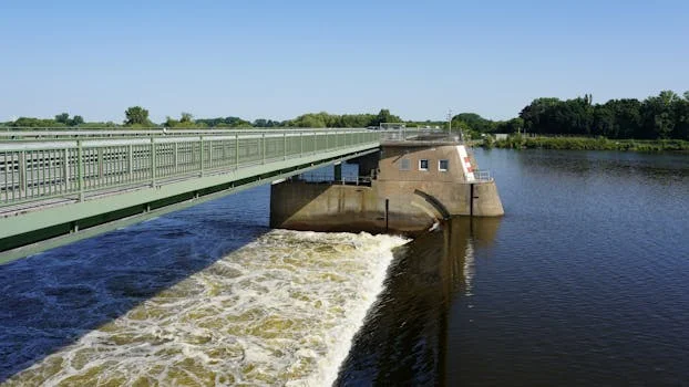
Reactive fixes stop symptoms; design and automation cut recurrence after primary clarifier troubleshooting finds the root cause. Upgrading to a high-efficiency lamella clarifier addresses chronic hydraulic overload, reaching 20–40 m/h surface loading rates and cutting footprint by up to 50% versus conventional tanks. Ultrasonic sludge-level sensors that start withdrawal at 0.5–0.6 m blanket depth limit septicity and gas formation. For variable or emulsified wastes, a PLC-controlled dosing system can feed coagulant at about 5–20 mg/L FeCl₃ and lift TSS removal by 15–25% during peaks.
Opaque launder covers block light and slow algae growth in effluent troughs. SCADA links for turbidity or streaming current support closed-loop polymer control. Write SOPs for each alarm and train operators on root-cause response rather than symptom chasing. When FOG spikes remain after skimming, place a Dissolved Air Flotation (DAF) System upstream so primary tanks see lower floatable load.
Field Selection Checklist and Cost Drivers
Plant engineers and EPC teams should confirm these items before changing setpoints or buying hardware:
- Measured HRT versus design 1.5–2.5 hours at current average and peak flow
- Surface loading versus the circular 30–48 or rectangular 20–40 m³/m²/day band for the tank type
- Blanket depth trend and withdrawal interval (target under two hours sludge residence)
- Weir levelness within ±2 mm and floor velocity below 0.1–0.3 m/s
- Drive oil water content below 0.5% and amp-draw trend versus baseline
- FOG concentration and skim interval; DAF need if FOG stays above about 200 mg/L
- Main cost drivers: aeration energy after poor TSS capture, polymer dose, sludge hauling, and unplanned drive repairs
Who this is for: operators and process engineers diagnosing primary tanks on industrial or municipal trains. Who should look elsewhere: teams sizing only tertiary filtration or membrane bioreactors without a primary solids problem. Next step: map your top symptom to the table above. Request a hydraulic and sludge-handling review if two or more metrics sit outside the ranges listed.
Frequently Asked Questions
What causes floating sludge in a primary clarifier?
Anaerobic gas in the sludge blanket lifts solids when withdrawal is too slow. Methane, CO₂, and hydrogen sulfide attach to floc and float it. Keep sludge residence under two hours, verify scrapers, and raise pump-out rate. Chemical oxidation helps if surface H₂S stays above 1 ppm after pumping changes.
How do I confirm short-circuiting in a clarifier?
A tracer dye or salt-pulse test shows short-circuiting when measured HRT is more than 20% below theoretical detention time. Inspect inlet baffles, weir levelness within ±2 mm, and corner sludge mounds that deflect flow. Repair seals on suction headers that bypass the settling path.
What causes bottom scour in a rectangular clarifier?
Floor velocities above about 0.3 m/s from failed or missing inlet baffles resuspend settled sludge. Repair the inlet, add an energy-dissipating inlet, or lengthen the distribution channel to cut approach velocity. Keep flight speed under 1.5 m/min so scrapers do not disturb the blanket.
When should I retrofit lamella plates instead of replacing the tank?
Retrofit lamella internals when the concrete tank is sound but surface loading exceeds design by about 30% or more. Plate packs raise effective settling area by roughly 5–10× in the same footprint and usually cost about one-third of new tank construction. Confirm structural capacity and sludge withdrawal before install.
Can primary clarifiers handle high FOG loads alone?
Primary clarifiers can skim FOG, but high loads need dedicated scum removal every 2–4 hours during production. Dairy, meat, and edible-oil wastes often need heated piping and upstream DAF when FOG exceeds about 200 mg/L. Gravity settling alone then leaves emulsified oil that elevates effluent TSS and fouls secondary biology.