How a dissolved air flotation process removes oil and FOG
A dissolved air flotation process removes free and emulsified oils, greases (FOG), and suspended solids (TSS) by releasing 20–50 µm micro-bubbles from a 40–70 psi recycle stream. Bubbles attach to chemically conditioned flocs, float them for skimming, and leave underflow often below 10 mg/L FOG and 30 mg/L TSS when dose and hydraulic loading match the load.
Plant engineers specify flotation when gravity separators cannot break emulsions or meet discharge limits. In food processing, petrochemical, and municipal pretreatment trains, a well-tuned unit commonly reaches 95%+ FOG and TSS removal at hydraulic retention times of 20–60 minutes. The <10 mg/L FOG and <30 mg/L TSS figures remain practical design targets; categorical EPA limits are industry-specific and often higher, as clarified in the efficiency section.
Why DAF Systems Outperform Gravity Separators for Industrial Wastewater
FOG and TSS remain frequent drivers of industrial pretreatment violations, especially where cleaners and proteins stabilize emulsions. Gravity separators work for free oils typically below about 100 mg/L FOG, but they struggle with emulsified fats and fine colloids. Dairy and meat plants often see influent FOG above 500 mg/L and TSS above 1,000 mg/L after clean-in-place cycles.
Most plants we size for those loads see gravity removal near 60% on emulsified streams, which is rarely enough for consistent compliance. With coagulant and flocculant conditioning, dissolved air flotation routinely reaches 95% or higher removal on the same water. Gravity units also need 2–4 hours retention and a large footprint, so they react poorly to surge flows in compact plants.
Density difference explains the gap. Free oil droplets large enough to rise under Stokes' law leave a quiet API-style bay. Emulsified droplets in the 1–20 µm range do not. Charge neutralization and polymer bridging grow those droplets into flocs that micro-bubbles can lift in minutes instead of hours.
| Parameter | Gravity Separator | DAF System |
|---|---|---|
| Target FOG (Influent) | <100 mg/L (free oils) | >100 mg/L (emulsified & free) |
| TSS Removal | Poor for fine particles | 95%+ (for fine & colloidal solids) |
| FOG Removal (Emulsified) | <50% | 95-98% |
| Retention Time | 2-4 hours | 20-60 minutes |
| Footprint | Large | Compact |
| Sensitivity to Flow Variation | High | Low-Medium (with proper control) |
When buyers compare free-oil hardware with flotation duty, a focused read on daf vs coalescence separator for oil removal clarifies cost and applicability. For emulsified FOG above roughly 100 mg/L, flotation is usually the safer primary step before biology or membranes.
Step-by-Step Engineering Process for Oil and Water Separation
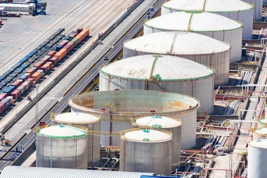
Industrial oily wastewater is clarified here in six physical-chemical steps that turn dissolved air into buoyant micro-bubbles. Operators who understand each step diagnose poor float quality faster than those who treat the tank as a black box.
- Step 1: Chemical Conditioning
Coagulants such as poly-aluminum chloride (PAC) or ferric chloride are typically dosed at 50–200 mg/L to neutralize charge on emulsified oils and fine solids. High-molecular-weight polyacrylamide flocculants then follow at 1–5 mg/L to build shear-resistant flocs. Most trains hold pH between 6.5 and 8.5 during this stage so metal salts and polymer work together. Flash mix is short; flocculation time is longer so flocs grow without shredding before the contact zone. - Step 2: Air Dissolution
Clarified effluent recycle, commonly 10–30% of influent flow, is pressurized in a saturator at 40–70 psi. Packed-bed saturators are frequent on industrial packages because packing increases air-water contact. Saturator hydraulic retention is typically 1–3 minutes so the recycle exceeds atmospheric saturation. Heavy FOG and solids loads usually push operators toward the higher end of that recycle band. - Step 3: Pressure Release
The pressurized recycle passes through a pressure-reduction valve or nozzle into the flotation tank. The sudden drop to atmospheric pressure drives dissolved air out of solution as uniform 20–50 µm bubbles. Henry's Law explains the effect: gas solubility rises with partial pressure, so depressurization creates a dense bubble cloud suited to floc attachment. Worn nozzles that create coarse bubbles cut collision probability and leave cloudy underflow. - Step 4: Bubble-Particle Attachment
Micro-bubbles mix with conditioned wastewater in the contact zone. Hydrophobic oil droplets attach readily; hydrophilic solids need floc bridges. Contact-zone hydraulic loading is often designed near 5–15 m/h with baffles that keep short-circuiting in check. Most plants we commission run at the lower end of that loading band when FOG is sticky and float must stay dry. - Step 5: Flotation and Skimming
Bubble-particle aggregates typically rise at 5–15 cm/min and form a float layer on the surface. Chain-and-flight, spiral, or reciprocating skimmers remove that layer based on solids loading and desired float dryness. Skimmer speed is commonly set between 0.5 and 2 m/min so water is not dragged into the float hopper. Too-fast skimming inflates sludge volume without improving effluent FOG. - Step 6: Effluent Clarification
Clarified water leaves under an underflow weir for biological treatment, discharge, or reuse polishing. Float solids are often 2–5% and go to thickening or dewatering. At this point the Dissolved Air Flotation (DAF) System has finished primary FOG and TSS capture and protected downstream units from oily shock loads.
Where flotation sits in a pretreatment process train
Flotation pretreatment for oily wastewater usually sits after screening and equalization and before biological treatment or membranes. A practical block diagram runs: equalization → chemical conditioning → contact/flotation → skim/float handling → clarified effluent to biology or polishing. That layout answers the common need for a pretreatment process diagram without treating flotation as a stand-alone black box.
Equalization dampens CIP spikes so coagulant demand stays stable across the shift. Chemical conditioning breaks emulsions before bubbles ever form. Float handling protects pumps and digesters from oily scum. If the next stage is MBR or RO, keeping FOG low here is cheaper than fighting membrane fouling later. Plants that skip equalization often chase phantom chemistry problems that are really hydraulic spikes.
Instrumentation that pays for itself includes influent and effluent FOG/TSS sampling points, saturator pressure transmitters, recycle flow meters, and pH at the flocculation tank. Without those four signals, operators guess which knob to turn when the float turns watery overnight. For whole-plant context, see integrated wastewater treatment plant design and efficiency data and MBR effluent quality benchmarks for post-DAF treatment.
DAF System Components: Engineering Specs and Design Considerations
DAF system performance depends on how the tank, saturator, recycle pump, compressor, skimmer, and dosing package are sized together. Spec sheets that list only tank volume without recycle pressure or hydraulic loading are incomplete for EPC review. Field experience shows undersized saturators fail emulsified FOG duty long before an undersized tank does.
The core components of a DAF unit for industrial wastewater include:
- Flotation Tank: Separation vessel sized for hydraulic loading of 5–15 m/h, depth typically 1.5–3 m, and retention of 20–60 minutes. Stainless steel 304/316 or FRP is selected from chloride, temperature, and budget constraints. Baffle geometry between contact and separation zones matters as much as plan area.
- Saturator: Pressure vessel that dissolves air into recycle water, often with PVC or stainless packing. Typical air-to-water ratios are 5–10% by volume with a packing pressure drop of 0.5–2 bar. Packed saturators are efficient but need clean recycle; dirty recycle favors unpacked designs with more maintenance margin.
- Recycle Pump: Centrifugal pump with VFD control holds 40–70 psi while moving about 10–30% of influent flow. NPSH margin and wire-to-water efficiency dominate long-term power cost. Cavitation here collapses bubble quality within minutes.
- Air Compressor: Oil-free compressors are preferred indoors. Capacity is commonly 0.1–0.3 m³/min per 100 m³/h of influent wastewater. Contaminated instrument air can reintroduce oil into a system built to remove it.
- Skimming System: Chain-and-flight suits heavy solids; spiral or reciprocating units favor compact layouts. Skimmer speed stays near 0.5–2 m/min. Beach angle and float hopper volume should match peak solids days, not average days.
- Chemical Dosing System: PLC metering pumps dose coagulant and flocculant and hold pH at 6.5–8.5. Our PLC-controlled chemical dosing systems for DAF optimization keep dose proportional to flow and turbidity feedback when influent swings after CIP.
| Component | Key Engineering Specification | Design Consideration / Material |
|---|---|---|
| Flotation Tank | Hydraulic Loading Rate: 5–15 m/h Depth: 1.5–3 m Retention Time: 20–60 min |
Material: Stainless Steel (304/316) or FRP for corrosion resistance |
| Saturator | Pressure: 40–70 psi Air-to-Water Ratio: 5–10% (by volume) Pressure Drop: 0.5–2 bar |
Packed bed design (PVC or stainless steel packing), 1–3 min retention time |
| Recycle Pump | Discharge Pressure: 40–70 psi Flow Rate: 10–30% of influent |
Centrifugal pump with VFD for pressure control; NPSH and efficiency are key |
| Air Compressor | Capacity: 0.1–0.3 m³/min per 100 m³/h influent | Oil-free, low-noise models preferred; reliable air supply |
| Skimming System | Skimmer Speed: 0.5–2 m/min | Type: Chain-and-flight (heavy solids) vs. spiral (compact, low maintenance) |
| Chemical Dosing | Coagulant Dosage: 50–200 mg/L Flocculant Dosage: 1–5 mg/L |
PLC-controlled metering pumps; pH adjustment (6.5–8.5) |
Real-World Efficiency: DAF Performance Data by Industry
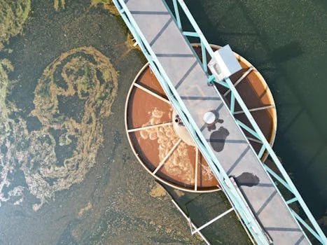
Industry performance for oily-water flotation still clusters around 95%+ FOG removal when coagulant demand is met and hydraulic loading stays inside design. Food plants with high protein emulsions, petrochemical oily water, and municipal FOG pretreatment show different influent ranges but similar removal ceilings when the float is kept dry and recycle pressure is stable.
According to US EPA 40 CFR 419.45, petroleum refining pretreatment standards set oil and grease at 100 mg/L maximum for the refinery contribution to a POTW. According to US EPA 40 CFR 423.12, steam-electric BPT tables list oil and grease at 20.0 mg/L and TSS at 100.0 mg/L for several wastestreams. The <10 mg/L FOG and <30 mg/L TSS figures remain useful DAF effluent targets that sit under those categorical numbers when the unit is chemically optimized.
Local POTW FOG limits for food processors often land near 100 mg/L as well, though permits vary by city. Designing to <10–30 mg/L FOG after flotation therefore builds headroom for sample variability and CIP days without rewriting chemistry every week.
- Food Processing (Dairy, Meat, Beverage): Influent FOG typically ranges from 300–800 mg/L and TSS from 500–1,500 mg/L. Flotation systems reliably achieve effluent quality of <10 mg/L FOG and <30 mg/L TSS, representing 95–98% removal. That headroom matters for surcharge control and biology protection.
- Petrochemical: Facilities often deal with oils at 200–1,000 mg/L and TSS at 200–800 mg/L. Units placed downstream of API separators commonly reach oil <15 mg/L and TSS <50 mg/L, with removal rates between 92–97%.
- Municipal Pre-Treatment: High-strength industrial discharges can bring FOG of 50–200 mg/L and TSS of 100–500 mg/L. Flotation can cut these to <20 mg/L FOG and <50 mg/L TSS at 85–95% removal, often outperforming primary clarifiers for FOG and fine solids.
- Pulp & Paper: Influent TSS often ranges from 1,000–3,000 mg/L from fibers and fillers. Flotation can reduce TSS below <100 mg/L at 90–95% removal and support fiber recovery where economics allow.
- Textile: Wastewater with COD 800–2,000 mg/L and TSS 300–1,000 mg/L from dyes and sizing agents can see 75–85% TSS removal, bringing effluent TSS below <50 mg/L and helping COD fall toward <200 mg/L before color polishing.
| Industry Sector | Typical Influent Range | Effluent (2025 Benchmark) | Removal Efficiency (FOG/TSS) |
|---|---|---|---|
| Food Processing | FOG 300–800 mg/L, TSS 500–1,500 mg/L | FOG <10 mg/L, TSS <30 mg/L | 95–98% |
| Petrochemical | Oil 200–1,000 mg/L, TSS 200–800 mg/L | Oil <15 mg/L, TSS <50 mg/L | 92–97% |
| Municipal Pre-Treatment | FOG 50–200 mg/L, TSS 100–500 mg/L | FOG <20 mg/L, TSS <50 mg/L | 85–95% |
| Pulp & Paper | TSS 1,000–3,000 mg/L | TSS <100 mg/L | 90–95% |
| Textile | COD 800–2,000 mg/L, TSS 300–1,000 mg/L | COD <200 mg/L, TSS <50 mg/L | 75–85% |
Selection tip for buyers comparing a daf oil separator against other hardware: start from influent FOG speciation (free vs emulsified), not from nameplate flow alone. Emulsion fraction drives chemical cost more than tank steel thickness does. Ask vendors for jar-test photos on your wastewater, not only on a generic oily-water recipe.
How do oil separator efficiencies compare?
Oil separator efficiency comparison starts with contaminant form: free oil, dispersed oil, or stable emulsion, plus TSS. Gravity units often remove under 50% of emulsified FOG. Coalescers commonly reach 70–90% on free and dispersed oils but clog when solids are high. DAF systems typically deliver 95–98% FOG removal on emulsified loads above 100 mg/L. Membrane polishing can exceed 99% FOG removal but at higher CAPEX, OPEX, and fouling risk.
- Gravity Separators: Best for free oils at low FOG (<100 mg/L) and large flows. Limits include poor emulsion performance, large footprint, and 2–4 hour retention.
- Coalescers: Compact and effective on free/dispersed oils, yet sensitive to solids blinding and weak on TSS.
- Membrane Systems (UF/RO): Aimed at ultra-low targets (<1 mg/L FOG) and reuse. High CAPEX/OPEX and fouling risk demand strong pretreatment. For polishing after flotation, consider Reverse Osmosis (RO) water purification systems.
- DAF Systems: Best for emulsified oils with FOG typically >100 mg/L and TSS >200 mg/L. Main trade-offs are chemical dependency and float handling.
Decision Framework: Use DAF when influent FOG exceeds 200 mg/L, TSS is above 500 mg/L, or stable emulsions are present. Gravity or coalescers can suffice for free oil at low FOG. Membranes are polishing tools after primary FOG capture, not first-stage emulsion breakers.
| Technology | Best For | Limitations | Typical FOG Removal |
|---|---|---|---|
| Gravity Separators | Free oils, low FOG (<100 mg/L), large flow rates | Poor with emulsions, large footprint, long retention time | <50% |
| Coalescers | Free and dispersed oils, small footprint | Clogging with solids, high maintenance, limited TSS removal | 70-90% |
| DAF Systems | Emulsified oils, high FOG/TSS (>100 mg/L), compact footprint, variable influent loads | Chemical dependency, sludge handling requirements | 95-98% |
| Membrane Systems (UF/RO) | Ultra-low effluent targets (<1 mg/L FOG), water reuse applications | High CAPEX/OPEX, significant fouling risk, extensive pre-treatment required | >99% |
For a deeper alternatives matrix on the same decision, review the sibling page covering a daf oil water separator versus competing unit processes with cost and compliance notes.
What drives oil water separator CAPEX?
Oil water separator CAPEX for DAF packages typically ranges from $50,000 to $500,000 at 10–300 m³/h, driven by materials, automation, chemical systems, and sludge handling—not tank volume alone. Stainless versus FRP, redundant pumps, and enclosed skimmers move quotes more than minor changes in listed hydraulic loading. OPEX usually falls between $0.10 and $0.50 per cubic meter, led by chemicals, recycle energy, and float disposal.
Buyers should request a line-item split for saturator design pressure, recycle pump VFD, coagulant storage, and dewatering. A cheap tank with an undersized saturator fails on emulsified FOG even if the steel looks heavy. For a worked cost model, see the 2025 DAF system cost breakdown and ROI calculator.
Cost drivers that surprise first-time buyers include heated polymer make-down in cold rooms, duplex chemical pumps for continuous duty, odor covers on food-plant float hoppers, and explosion-proof electrics on hydrocarbon oily-water packages. Those items rarely appear in a bare tank quote but show up on every complete installation budget.
Selection checklist before issuing a PO:
- Confirm free vs emulsified FOG fraction with jar tests on real CIP samples.
- Match recycle ratio and saturator pressure to peak FOG and TSS, not average day only.
- Set hydraulic loading inside 5–15 m/h at the design peak hour.
- Specify float solids target (often 2–5%) and the downstream press or dryer.
- Require pH control band 6.5–8.5 with documented coagulant/flocculant dose ranges.
- Verify materials against chloride, temperature, and cleaning chemicals.
- Define effluent FOG/TSS guarantees against the actual permit or POTW local limit.
Operational Best Practices: Maximizing DAF Efficiency and Longevity
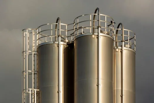
DAF uptime tracks jar-test discipline and saturator cleanliness more than brochure features. Plants that re-check chemistry after every product-campaign change keep effluent FOG stable; plants that freeze doses for months chase float quality with skimmer speed alone. A short weekly checklist beats a thick binder nobody opens.
- Chemical Optimization: Run jar tests on 500 mL samples with 1–5 minutes mix and 10–30 minutes observation. Hold pH between 6.5 and 8.5 while scanning coagulant and flocculant doses. Record the winning dose against influent FOG so night shifts inherit a number, not a guess.
- Bubble Size Control: Keep saturator pressure at 40–70 psi and air-to-water recycle near 5–10% when verifying 20–50 µm bubbles. Microscopy or laser diffraction helps after nozzle changes. Coarse white foam usually means nozzle wear or pressure loss, not “extra air helping.”
- Flow Rate Management: Stay inside 5–15 m/h hydraulic loading. Use VFDs on recycle pumps so pressure does not collapse during low night flows. If influent drops 40%, cut recycle speed to hold pressure rather than flooding the tank with excess hydraulic load.
- Sludge Handling: Set skimmer speed at 0.5–2 m/min to avoid watery float. Target 2–5% float solids before dewatering. For pressing, use high-efficiency sludge dewatering for DAF float layer. Hauling watery float is one of the fastest ways to erase OPEX savings.
- Maintenance: Clean saturator packing weekly, inspect skimmer blades monthly, and service pumps and compressors quarterly. Keep spare nozzles and a spare recycle seal kit on the shelf; both fail on holiday weekends.
- Troubleshooting: Poor flotation usually traces to dose, pH, or weak bubble generation. Excess sludge volume often means the skimmer runs too fast or chemistry is off. Cloudy effluent with a thick float points to hydraulic short-circuiting more often than a “bad polymer brand.”
Who this is for / Next step
This guide is for plant engineers, EPC designers, and procurement teams sizing FOG pretreatment where emulsions defeat gravity tanks. Look elsewhere if the stream is only free oil below about 100 mg/L FOG with almost no TSS—gravity or coalescing hardware may be enough. If you already have influent FOG/TSS, flow, and a permit limit, send those numbers through our DAF sizing and quote request so recycle ratio and tank loading can be checked against your peak hour, not a catalog average.
Frequently Asked Questions
What is the typical retention time for a DAF system?
Retention time for a DAF system typically ranges from 20 to 60 minutes at hydraulic loading rates of 5–15 m/h. Shorter times near 20–30 minutes suit high-flow, lower-solids feeds. Longer times near 40–60 minutes are used for high FOG/TSS loads or stubborn emulsions so contact and rise can finish before the underflow weir.
How much does a DAF flotation package cost?
CAPEX commonly spans $50,000 to $500,000 for 10–300 m³/h packages, depending on stainless versus FRP, automation, dosing, and sludge options. OPEX usually sits between $0.10 and $0.50 per cubic meter from chemicals, recycle energy, and float disposal. Detailed splits belong in a site-specific quote rather than a single catalog price.
Can DAF systems handle emulsified oils?
Yes. DAF systems are built for emulsified oils once coagulants and flocculants destabilize the droplets. Micro-bubbles then attach to the conditioned flocs and float them. Removal often exceeds 95% for emulsified FOG, while gravity separators typically stay below 50% on the same emulsions.
What are the main failure modes of a DAF system?
Common failure modes include saturator clogging from dirty recycle or neglected packing, skimmer jamming from debris, and chemical over- or under-dosing that collapses flotation. Weekly packing checks, jar testing after waste changes, and stable saturator pressure prevent most of those failures before effluent FOG drifts out of permit.
How does DAF compare to membrane bioreactors (MBRs)?
DAF and MBRs serve different roles in a treatment train. DAF is physical-chemical FOG and TSS pretreatment. MBRs combine biology with membranes for BOD and COD polishing. DAF usually costs less to own but needs chemicals, while MBRs need more energy and membrane care. DAF often protects MBR membranes from FOG shock loads.
Related Equipment
- Dissolved air flotation (DAF) system for industrial wastewater — view specifications, capacity range, and technical data
Need a customized solution? Request a free quote with your specific flow rate and pollutant parameters.