Why Monocrystalline Silicon Wastewater Demands Specialized Treatment
Monocrystalline silicon production generates three primary wastewater streams characterized by high acidity and complex mineral loads: saw damage removal (SDR), phosphorus silicate glass (PSG) etching, and emitter formation. Unlike multicrystalline processes that rely heavily on acid texturing, monocrystalline production utilizes alkaline texturing but produces significantly higher concentrations of dissolved silica and fluoride during the initial wafering and cleaning stages. Typical raw influent from these lines contains fluoride levels between 500 and 2,000 mg/L, Total Suspended Solids (TSS) ranging from 300 to 1,500 mg/L, and Chemical Oxygen Demand (COD) between 800 and 3,000 mg/L (HydropureWater field data, 2025).
Generic industrial wastewater systems frequently fail in solar manufacturing environments due to three specific technical bottlenecks. First, the high concentration of hydrofluoric acid (HF) used in PSG etching leads to rapid corrosion of standard concrete tanks and non-specialized metal components. Second, dissolved silica (SiO2) from the SDR process, often reaching 100–300 mg/L, causes irreversible scaling on reverse osmosis membranes if not managed through specific pre-treatment. Third, regulatory frameworks like China’s GB 8978-1996 impose strict discharge limits, such as fluoride levels below 10 mg/L and TSS below 70 mg/L, which are unattainable through simple pH neutralization alone.
Economic pressures further necessitate specialized engineering solutions for silicon wafer wastewater treatment. In major solar manufacturing hubs like Jiangsu, China, or northern Malaysia, water scarcity has driven industrial water costs upward, while hazardous waste disposal fees for calcium fluoride (CaF2) sludge have surged to $200–$400 per ton. For a facility producing 5GW of monocrystalline cells annually, the ability to recover and reuse 95% or more of process water is no longer a sustainability goal but a requirement for operational profitability.
| Wastewater Stream Source | Primary Contaminants | Typical Concentration (mg/L) | Treatment Challenge |
|---|---|---|---|
| Saw Damage Removal (SDR) | HF, HNO3, Dissolved Silica | F: 800-1,500; SiO2: 200+ | Severe membrane scaling |
| PSG Etching | HF, HCl, Surfactants | F: 1,000-2,000; COD: 1,500+ | High acidity, foam generation |
| Emitter Formation | Phosphoric Acid, Isopropanol (IPA) | PO4: 50-150; COD: 2,000+ | Nutrient loading, high COD |
| Texturing & Rinsing | KOH, IPA, Silicates | pH: 11-13; TSS: 300-600 | High alkalinity, fine particulates |
Hybrid ZLD System Design: Step-by-Step Process for 99.8% Recovery
A hybrid Zero Liquid Discharge (ZLD) configuration for monocrystalline facilities integrates chemical precipitation, dissolved air flotation, membrane bioreactors, and reverse osmosis to achieve a cumulative water recovery rate of 99.8%. This multi-stage approach is essential because no single technology can simultaneously address the ionic, organic, and particulate loads present in solar cell effluent. The process begins with an equalization tank where high-concentration streams are buffered to prevent shock loading on downstream components.
The first stage involves a precision chemical dosing for fluoride precipitation and pH adjustment. By raising the pH to 8.5–9.0 using calcium hydroxide (Ca(OH)2) at a 1.2–1.5× stoichiometric ratio, fluoride is converted into insoluble CaF2. This is followed by a high-efficiency DAF system for TSS and oil removal in silicon wastewater. The DAF unit utilizes microbubbles (30–50 μm) and a hydraulic retention time of 15–20 minutes to achieve 92% TSS reduction, significantly lowering the solids load before biological treatment.
Secondary treatment utilizes an MBR system for biological degradation and pathogen removal in solar cell wastewater. The MBR employs PVDF membranes with a 0.1 μm pore size, maintaining a Mixed Liquor Suspended Solids (MLSS) concentration of 8,000–12,000 mg/L. This high biomass density is critical for degrading complex organics like Isopropanol (IPA) used in texturing. Finally, a multi-stage RO system for 95% water recovery in monocrystalline silicon wastewater projects polishes the water, reducing Total Dissolved Solids (TDS) to below 50 mg/L, making it suitable for reuse in texturing baths.
The system flow follows this sequence: Influent → Equalization → pH Adjustment/Coagulation → DAF → MBR → RO → Evaporator (for ZLD) → Reuse. To prevent silica scaling, which is the leading cause of RO failure in solar plants, the design includes continuous dosing of polyacrylate-based antiscalants and maintains a recovery rate per stage that keeps silica concentrations below 150 mg/L in the reject stream. Sludge generated from the precipitation stage is processed through a filter press to produce a dry cake (30-40% solids) for disposal or potential recycling in the cement industry.
| Process Stage | Key Engineering Specification | Removal Target | Critical Design Factor |
|---|---|---|---|
| Pre-treatment | Ca(OH)2 Dosing (1.2-1.5x) | 95% Fluoride | pH control precision (±0.1) |
| Primary (DAF) | 30-50 μm Microbubbles | 92% TSS | Surface loading rate < 5 m/h |
| Secondary (MBR) | PVDF Membrane (0.1 μm) | 95% COD | Flux rate (15-25 LMH) |
| Tertiary (RO) | High-Rejection Polyamide | 99% TDS | Silica scaling inhibition |
Parameter Table: Influent vs. Effluent Specs for Monocrystalline Wastewater
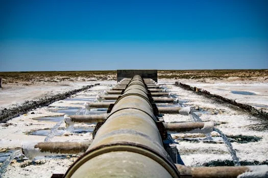
Engineered effluent targets for monocrystalline silicon facilities must align with China’s GB 8978-1996 standards, specifically mandating fluoride levels below 10 mg/L and Total Suspended Solids (TSS) below 70 mg/L. However, for plants targeting high reuse rates, the internal "Effluent Target" is often much stricter than regulatory minimums to prevent contamination of the production line. The following table outlines the performance metrics for a standard 2025-spec hybrid system designed by HydropureWater.
| Parameter | Influent Range (mg/L) | Effluent Target (mg/L) | Removal Efficiency | GB 8978-1996 Limit |
|---|---|---|---|---|
| Fluoride (F-) | 500 – 2,000 | < 8 | 98.5% – 99.6% | < 10 |
| TSS | 300 – 1,500 | < 10 | 97% – 99% | < 70 |
| CODcr | 800 – 3,000 | < 60 | 92% – 98% | < 100 |
| pH | 2.0 – 4.0 | 7.0 – 8.0 | N/A | 6.0 – 9.0 |
| Silica (SiO2) | 100 – 300 | < 5 | 95% – 98% | No Limit |
| Total Phosphorus | 20 – 150 | < 0.5 | 99% | < 0.5 |
| Oil & Grease | 50 – 200 | < 5 | 90% + | < 10 |
Achieving these targets requires a dual-loop control system. The primary loop manages the chemical precipitation of fluoride, while the secondary loop monitors the conductivity and silica levels of the RO permeate. For high-salinity wastewater treatment solutions for wafer fabs, ion exchange units may be added after the RO stage if ultrapure water (UPW) quality is required for final rinsing steps.
Cost Breakdown: CAPEX, OPEX, and ROI for Hybrid ZLD Systems
The total cost of ownership for a 100 m³/h hybrid ZLD system typically ranges between $1.2M and $2.5M in capital expenditure (CAPEX), with operational costs (OPEX) stabilizing between $0.80 and $1.50 per cubic meter of treated water. CAPEX is heavily influenced by the choice of membrane materials and the degree of automation required for the durable filter press for sludge dewatering and chemical dosing units. A breakdown of the investment reveals that the MBR and RO stages account for nearly 60% of the total equipment cost due to the high price of specialized chemical-resistant membranes.
OPEX is dominated by chemical consumption and energy. Precision dosing of Ca(OH)2, coagulants, and antiscalants typically costs $0.20–$0.40/m³. Energy requirements for high-pressure RO pumps and MBR aeration add another $0.30–$0.60/m³. However, these costs are offset by the significant savings in raw water procurement and discharge fees. In regions where hazardous waste disposal is mandated for fluoride sludge, the ROI is accelerated by the efficiency of the dewatering process, which reduces the volume of waste transported off-site.
| Cost Category | Estimated Cost (100 m³/h System) | % of Total | Key Drivers |
|---|---|---|---|
| CAPEX: Pre-treatment & DAF | $300,000 – $500,000 | 20% – 25% | Tank materials, DAF pump specs |
| CAPEX: MBR & RO Units | $700,000 – $1,500,000 | 55% – 60% | Membrane surface area, automation |
| OPEX: Chemicals | $0.20 – $0.40 / m³ | 30% | Fluoride load, silica levels |
| OPEX: Energy | $0.30 – $0.60 / m³ | 45% | RO pressure, aeration demand |
| OPEX: Maintenance | $0.15 – $0.30 / m³ | 25% | Membrane replacement, CIP freq |
For a plant in a high-cost water zone (e.g., $2.50/m³ for industrial water), a 100 m³/h system operating at 90% recovery saves approximately $1.9M annually in water costs. When combined with avoided disposal fees of $0.75/m³, the total annual savings can exceed $2.5M, leading to a payback period of 3 to 5 years. Hidden costs, such as a 15-20% increase in energy use due to membrane fouling, can be mitigated through rigorous Clean-In-Place (CIP) protocols every 3–6 months.
Decision Framework: Choosing the Right System for Your Plant
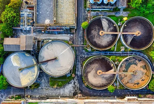
Selecting the optimal wastewater treatment architecture requires a three-tier evaluation based on local discharge regulations, water scarcity indices, and the specific chemical footprint of the production line. Engineering managers must decide whether their objective is simple regulatory compliance or a comprehensive ZLD strategy aimed at maximum resource recovery. The decision framework below categorizes systems based on these objectives.
| System Tier | Configuration | Recovery Rate | Best For... |
|---|---|---|---|
| Tier 1: Compliance-Only | Precipitation + DAF | 60% – 80% | Abundant water, lax reuse mandates |
| Tier 2: Water Reuse | Precipitation + DAF + MBR | 90% – 95% | Standard monocrystalline cell fabs |
| Tier 3: ZLD Hybrid | Tier 2 + RO + Evaporator | 99% + | Zero-discharge zones, high ROI potential |
The decision tree for procurement leads follows three logical gates. First, if local fluoride limits are below 10 mg/L, a minimum of Tier 1 is required. Second, if the cost of incoming water exceeds $1.50/m³ or if corporate sustainability mandates require >90% recovery, Tier 2 is the technical baseline. Third, if the plant is located in a "Zero Liquid Discharge" industrial park or if hazardous waste disposal fees for liquid waste exceed $0.75/m³, the additional CAPEX for a Tier 3 ZLD system is financially justified.
Before finalizing a system selection, engineering teams should use the following checklist:
- Footprint: Does the DAF and MBR configuration fit within the allocated utility space?
- Scalability: Can the dosing system and RO racks handle a 20-30% increase in production capacity?
- Chemical Compatibility: Are all wetted parts in the PSG treatment line rated for concentrated HF?
- Membrane Life: Does the supplier provide a 3-year performance guarantee against silica scaling?
Case Study: 2025 Monocrystalline Silicon Plant in Jiangsu Achieves 99.8% Recovery
A 150 m³/h monocrystalline silicon manufacturing facility in Jiangsu Province successfully implemented a hybrid ZLD system in early 2025, reaching a 99.8% water recovery rate and achieving full ROI within 38 months. The plant faced extreme pressure from local environmental bureaus to reduce fluoride discharge and was struggling with high municipal water costs. The influent profile was challenging: fluoride concentrations peaked at 1,200 mg/L, and COD from texturing additives reached 2,500 mg/L.
The solution provided by HydropureWater utilized a four-stage treatment train. High-concentration HF streams were segregated and treated with a dedicated calcium-based precipitation unit before joining the main flow in the DAF unit. The MBR stage successfully reduced COD to <100 mg/L, protecting the downstream RO membranes from organic fouling. To combat the 220 mg/L of dissolved silica, the plant implemented a specialized antiscalant dosing regimen and a staggered RO cleaning schedule.
Post-implementation data showed that the effluent fluoride levels were consistently below 8 mg/L, comfortably meeting GB 8978-1996 standards. More importantly, 149.7 m³/h of the treated water was returned to the texturing and rinsing baths, reducing the plant's reliance on municipal water by 70%. The plant manager noted, "The hybrid system eliminated our hazardous liquid waste disposal fees entirely. By converting the fluoride into a dry, manageable sludge cake, we turned a major compliance risk into a predictable operational expense."
Frequently Asked Questions
Q: What is the biggest challenge in treating monocrystalline silicon wastewater?
A: Silica scaling in RO membranes is the primary technical hurdle. Monocrystalline wastewater contains 100–300 mg/L of silica from saw damage removal. Without specific antiscalant dosing (e.g., 5–10 mg/L polyacrylate) and frequent CIP every 3–6 months, membranes can fail within weeks. (HydropureWater field data, 2025).
Q: How much does a monocrystalline wastewater treatment system cost?
A: For a 100 m³/h system, CAPEX ranges from $1.2M to $4M depending on the recovery target. OPEX is typically $0.80–$1.50/m³. ZLD systems have higher upfront costs but often pay for themselves in 3–5 years through water savings and avoided disposal fees.
Q: Can treated water be reused in solar cell production?
A: Yes. RO permeate with a TDS <50 mg/L is ideal for texturing baths and early-stage rinsing. For the final rinse, this water can be further polished through an EDI unit. MBR effluent is suitable for non-critical uses like cooling towers or scrubber make-up water.
Q: What are the regulatory limits for fluoride in monocrystalline wastewater?
A: Under China GB 8978-1996, the limit is <10 mg/L. In the European Union, the Industrial Emissions Directive (2010/75/EU) often requires <5 mg/L for new installations. Hybrid solar cell wastewater treatment projects with 99% recovery blueprints can achieve <2 mg/L.
Q: How often do membranes need replacement in these systems?
A: MBR membranes typically last 5–7 years with proper maintenance. RO membranes in silicon applications last 3–5 years. Life expectancy is highly dependent on the efficiency of the pre-treatment stage and the consistency of the antiscalant dosing.