Why Solar Cell Wastewater Treatment Demands a Hybrid Approach
Solar cell wastewater treatment projects in 2025 require hybrid systems to handle high TSS (500–2,000 mg/L), COD (800–3,000 mg/L), and silica (100–500 mg/L) from PV manufacturing. Combining solar-powered energy with advanced treatment technologies like MBR (99% TSS removal) and RO (95% recovery) achieves zero liquid discharge (ZLD) while cutting energy costs by up to 40%. For example, a 200kW solar thermal system can recover 90% of wastewater as distilled water, reducing sludge moisture from 80% to 10% (SolarPACES, 2019). Manufacturing processes for crystalline silicon and thin-film solar cells generate complex waste streams containing hydrofluoric acid, nitric acid, and various heavy metals like lead and cadmium. Conventional treatment plants often fail because silica (SiO2), a primary byproduct of wafer sawing and grinding, causes rapid irreversible fouling of filtration membranes and scale formation in piping.
The energy intensity of photovoltaic (PV) wastewater treatment is a significant operational hurdle, with aerobic biological systems typically consuming 1.5–3 kWh per cubic meter of treated water. In large-scale manufacturing environments, this translates to millions of dollars in annual utility costs. Data from the Traverse City wastewater project indicates that integrating solar arrays can provide a 10% energy offset, saving approximately $41,000 annually for municipal-scale operations, a figure that scales significantly in industrial PV manufacturing. Standalone solar treatment—relying purely on evaporation or basic filtration—cannot meet the stringent 2025 discharge limits for heavy metals or chemical oxygen demand (COD). Consequently, a hybrid approach is mandatory, utilizing mechanical-chemical pretreatment to stabilize the influent before passing it through high-efficiency biological and membrane stages powered by renewable energy.
Silica concentrations in solar cell effluent typically range from 100 to 500 mg/L, which exceeds the solubility limit at neutral pH, leading to the precipitation of colloidal silica. Standard sedimentation and chemical dosing are often insufficient for these concentrations, requiring specialized high-efficiency DAF system for TSS and silica removal to ensure the downstream membrane bioreactor (MBR) and reverse osmosis (RO) units are protected from scaling. By integrating solar PV to power these mechanical processes and solar thermal energy for final brine evaporation, manufacturers can achieve a closed-loop water cycle that mitigates both environmental risk and rising energy prices.
Engineering Specs for Solar Cell Wastewater: Influent, Effluent, and Treatment Targets
Engineering specifications for solar cell wastewater treatment systems must account for high concentrations of abrasive suspended solids and dissolved reactive silica that characterize PV manufacturing. Effective system design begins with a detailed characterization of the influent, which typically includes hydrofluoric acid from etching and various organic surfactants from wafer cleaning. To achieve zero liquid discharge (ZLD), the system must target 95–99% water recovery, necessitating a multi-stage approach that addresses both particulate and dissolved contaminants. The following table outlines the typical engineering parameters for a modern solar cell wastewater treatment project based on global industrial standards (per EnviroChemie and EPA guidelines).
| Parameter | Influent Range | Effluent Target (Reuse/ZLD) | Removal Efficiency | Compliance Standard |
|---|---|---|---|---|
| Total Suspended Solids (TSS) | 500–2,000 mg/L | < 5 mg/L | > 99% | China GB 3544-2008 / US EPA |
| Chemical Oxygen Demand (COD) | 800–3,000 mg/L | < 50 mg/L | > 98% | EU Industrial Emissions Directive |
| Silica (SiO2) | 100–500 mg/L | < 10 mg/L | > 97% | Internal Reuse Specs |
| Fluoride (F-) | 20–150 mg/L | < 1 mg/L | > 99% | Global Semiconductor Standards |
| Lead (Pb) | 0.5–5.0 mg/L | < 0.1 mg/L | > 98% | US EPA / China GB |
| Cadmium (Cd) | 0.1–1.0 mg/L | < 0.01 mg/L | > 99% | EU REACH / US EPA |
| pH | 2.0–11.0 | 6.5–8.5 | N/A | General Discharge Limits |
Silica removal is the most critical engineering challenge in this spec. High-density sludge (HDS) processes or specialized coagulation using magnesium salts at high pH (typically >10.5) are required to reduce silica to levels manageable for membrane systems. Failure to address silica in the pretreatment stage results in membrane replacement cycles shortening from years to months. effluent targets vary significantly by jurisdiction; for instance, China’s GB 3544-2008 standard permits a TSS of < 70 mg/L for discharge, whereas US EPA guidelines often mandate < 30 mg/L. For manufacturers aiming for internal water reuse, the targets are even more stringent, often requiring a total dissolved solids (TDS) level of less than 50 mg/L to prevent interference with sensitive solar cell fabrication steps.
To meet these targets, an engineering blueprint for 99.9% recovery in PV wastewater must be followed, incorporating real-time monitoring of fluoride and heavy metal concentrations. This ensures that the chemical dosing remains optimal even when production shifts between different solar cell architectures, such as TOPCon or HJT, which produce varying pollutant loads.
Hybrid System Design: Combining Solar Power with Advanced Treatment Technologies
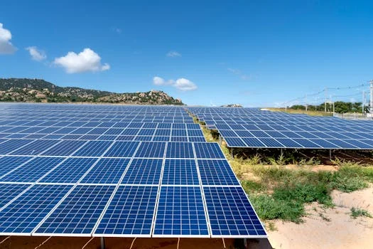
Hybrid system design for solar cell wastewater treatment integrates photovoltaic energy and solar thermal heat with a three-stage mechanical-biological-membrane process. This configuration ensures that the energy-intensive components—such as aeration blowers, high-pressure RO pumps, and sludge dryers—are powered by the very technology the plant manufactures. The first stage involves pretreatment using a high-efficiency DAF system for TSS and silica removal. In this stage, air is dissolved under pressure and then released into the wastewater, causing fine particles of silica and heavy metal precipitates to float to the surface for mechanical skimming. This reduces the TSS load by up to 95% before biological treatment.
The second stage utilizes an MBR system for COD/BOD removal and near-reuse-quality effluent. The MBR combines conventional activated sludge treatment with membrane filtration, allowing for high biomass concentrations (MLSS of 8,000–12,000 mg/L). This high concentration enables the system to break down complex organic surfactants used in solar cell texturing. By using solar PV (typically 50–500 kW depending on plant scale), the facility can power the aeration grids required to keep the MBR membranes clean and the bacteria alive, reducing grid dependency by 20–40%.
The third stage is the polishing and recovery phase, where an RO system for silica and heavy metal removal in PV wastewater extracts high-purity water from the effluent. To achieve ZLD, the RO brine is sent to a solar thermal evaporation unit. Utilizing 200kW Concentrated Solar Power (CSP) systems, the plant can apply direct thermal energy to evaporate the remaining liquid, reducing sludge moisture from an 80% "cake" to a 10% dry solid. This process, as documented by SolarPACES, recovers 90% of the wastewater as distilled water, which can be recirculated back into the manufacturing line. The process flow follows a linear path: Influent → pH Adjustment/Coagulation → DAF → MBR → RO → Solar Thermal Evaporation → Zero Liquid Discharge.
Comparison Table: Solar-Powered vs. Conventional Wastewater Treatment for PV Manufacturing
Procurement managers must weigh the higher initial capital expenditure (CAPEX) of hybrid systems against the significantly lower operational expenditure (OPEX) and superior compliance reliability. While conventional aerobic systems are cheaper to install, their high energy consumption and inability to handle concentrated silica streams often lead to "hidden" costs, such as frequent membrane cleanings and high sludge disposal fees. The following table compares the performance and financial metrics of solar-powered hybrid systems against conventional alternatives.
| Parameter | Solar-Powered Hybrid (DAF+MBR+RO+PV) | Conventional Aerobic | Conventional Anaerobic | Notes |
|---|---|---|---|---|
| CAPEX ($/m³) | $2,500 – $4,500 | $1,200 – $2,000 | $1,500 – $2,500 | Hybrid includes PV/Thermal arrays |
| OPEX ($/m³) | $0.40 – $0.65 | $0.85 – $1.30 | $0.70 – $1.10 | Hybrid saves on energy/sludge |
| Energy Consumption | 0.8 – 1.2 kWh/m³ (Net) | 1.5 – 3.0 kWh/m³ | 1.0 – 2.0 kWh/m³ | Solar offsets 20-40% of grid use |
| TSS Removal (%) | > 99% | 85 – 90% | 70 – 80% | MBR/DAF synergy is superior |
| Silica Removal (%) | > 97% | < 40% | < 20% | Conventional fails without RO/DAF |
| Sludge Production | Low (Dried to 10%) | High (80% moisture) | Medium (75% moisture) | Solar thermal reduces volume by 70% |
| Compliance Reliability | High | Medium | Low | Hybrid handles load variability better |
The data highlights that while a solar-powered hybrid system requires a higher upfront investment, the reduction in OPEX—driven by a 30% lower energy cost and 70% reduction in sludge disposal volume—results in a more sustainable financial model. the 99% TSS removal and high silica rejection rates ensure that the plant remains in compliance even as global discharge standards tighten. This technical superiority is further explored in our real-world case study of a hybrid solar wastewater system, which details the performance of these systems under actual factory loads.
Cost Breakdown and ROI: Solar Cell Wastewater Treatment Projects
Investing in a solar cell wastewater treatment project requires a clear understanding of the return on investment (ROI) beyond simple environmental compliance. For a typical plant processing 100 m³/h, the CAPEX is distributed across the solar PV installation ($1.5–$3 per watt), the DAF pretreatment unit ($50,000–$150,000), the MBR biological stage ($200,000–$500,000), and the RO recovery system ($100,000–$300,000). While these figures represent a substantial initial outlay, the operational savings are dual-pronged: energy reduction and water recovery.
The OPEX of a hybrid system is primarily composed of chemical costs ($0.10–$0.30/m³), membrane replacement ($0.05–$0.20/m³), and residual energy costs from the grid ($0.05–$0.15/kWh). However, by reusing 95% of the treated water, a 100 m³/h plant saves approximately 800,000 cubic meters of fresh water annually. At an average industrial water rate of $1.50/m³, this equates to $1.2M in annual savings. When combined with the $150,000 saved in energy costs (based on a 10% offset like the Traverse City project), the total annual savings can exceed $1.35M. For a total project CAPEX of $2.5M, this results in a payback period of approximately 3.5 years.
Financial feasibility is further enhanced by global grants and tax incentives. For instance, the City of Traverse City received $1.68M from the Michigan Low Carbon Energy Infrastructure grant, and similar subsidies exist in China for ZLD industrial projects. In the United States, the Inflation Reduction Act provides significant tax credits for solar installations used in industrial water treatment, often covering up to 30% of the PV system cost. This makes the engineering blueprint for 99.9% recovery in PV wastewater not just an environmental necessity but a fiscally responsible strategy for 2025.
Compliance and Risk Mitigation: Meeting Global Discharge Standards
Maintaining compliance in the solar industry is a moving target as regulatory bodies increasingly focus on "forever chemicals" and heavy metal leaching. Hybrid systems mitigate these risks by providing multiple barriers of protection. The MBR handles organic pollutants, the RO system removes dissolved solids and metals, and the solar-powered evaporation stage ensures that no liquid waste ever leaves the site. The following table compares current global discharge standards for the solar manufacturing sector.
| Regulator | TSS (mg/L) | COD (mg/L) | Silica (mg/L) | Lead (mg/L) | Fluoride (mg/L) |
|---|---|---|---|---|---|
| China GB 3544-2008 | < 70 | < 100 | N/A | < 0.2 | < 10 |
| US EPA (General) | < 30 | < 120 | N/A | < 0.1 | < 4 |
| EU IED (Solar) | < 20 | < 50 | < 20 | < 0.05 | < 2 |
| India CPCB | < 100 | < 250 | N/A | < 0.1 | < 2 |
Risk mitigation strategies must prioritize the prevention of silica scaling in RO membranes. This is achieved through automated pH adjustment and the use of specialized antiscalants. Real-time monitoring of influent conductivity and turbidity allows the hybrid system to divert "slug loads"—sudden spikes in pollutant concentration—to buffer tanks, preventing the biological MBR from being overwhelmed. As noted in global discharge standards for solar industry wastewater, achieving consistent compliance requires a system that can adapt to the 20–100% flow variability common in manufacturing scale-ups. Case studies from EnviroChemie confirm that solar industry projects utilizing these hybrid designs consistently achieve 99% compliance with even the strictest EU standards.
Frequently Asked Questions
What is the biggest challenge in treating solar cell wastewater?
The primary challenge is silica (SiO2) fouling. Concentrations of 100–500 mg/L are common in solar manufacturing. If not removed via coagulation and a high-efficiency DAF system for TSS and silica removal, silica will precipitate on membranes, causing permanent damage and reducing water recovery rates.
How much energy can solar power save in a wastewater treatment plant?
Solar PV can offset 10–40% of the total energy consumption of a treatment plant. In the Traverse City case, a solar array saved $41,000 per year, representing a 10% offset. For industrial-scale plants with larger footprints for solar arrays, the savings can be significantly higher, especially when using solar thermal for sludge drying.
What is the typical payback period for a solar-powered hybrid system?
The typical payback period is 3 to 5 years. This is calculated by combining energy savings, the elimination of water procurement costs through 95% reuse, and reduced sludge disposal fees. A 100 m³/h plant with a $2.5M CAPEX can see annual savings of over $700,000 in optimal conditions.
Are there grants available for solar wastewater projects?
Yes. Many regions offer subsidies for Zero Liquid Discharge (ZLD) and renewable energy integration. Examples include the Michigan Low Carbon Energy Grant ($1.68M) and various green manufacturing subsidies in China and the EU. The US Inflation Reduction Act also provides tax credits for industrial solar applications.
Can solar-powered systems handle variable wastewater loads from PV manufacturing?
Yes. Hybrid systems are specifically designed with buffer tanks and automated controls to handle variability. The combination of DAF, MBR, and RO provides multiple treatment barriers that can be adjusted in real-time to handle flow fluctuations ranging from 20% to 100% of design capacity.