Why Industrial Plants Automate Chemical Dosing
Chemical dosing systems inject coagulants, pH adjusters, or disinfectants into a process stream under closed-loop control. Sensors measure pH, turbidity, or flow; a PLC calculates the dose; a metering pump injects chemical; feedback trims the rate. Industrial pumps typically hold ±0.5% to ±1.0% accuracy when sized mid-curve.
Manual batching remains common on older skids, yet it drives overuse and permit risk. Operators often over-dose by up to 40% to cover influent swings, and pH can drift by ±1.5 units between grabs. Handling corrosive reagents such as sulfuric acid or sodium hypochlorite also raises exposure risk during drum transfers and day-tank fills.
Discharge rules reinforce the shift to closed-loop control. Under the U.S. NPDES program and the EU Industrial Emissions Directive 2010/75/EU, plants must stay inside fixed effluent limits.A food processing plant cut coagulant spend by 28% and stopped permit fines after replacing manual batches with an automated skid. The control loop is fixed: Detection → Calculation → Dosing → Feedback.
Core Components of a Chemical Dosing System: Engineering Specs and Roles
System reliability depends on matching pump type, tank materials, and sensor fidelity to the chemistry in use. Wrong elastomers or an undersized pump curve shorten service life. An Automatic Chemical Dosing System typically packages these parts on one skid for continuous industrial duty.
Dosing Pumps: Peristaltic pumps (0.1–10,000 L/h) offer ±0.5% accuracy and suit shear-sensitive polymers or abrasive slurries. Diaphragm pumps (0.5–20,000 L/h) provide ±1% accuracy and remain the standard for high-pressure duty. For concentrated PAM and other high-viscosity reagents, progressive cavity pumps hold steady flow against high back-pressure.
Storage and Containment: Day tanks are usually sized for 3–5 days of autonomous supply. HDPE fits most acids; 316L stainless steel is required for selected oxidizers. Earlier vendor guidance often cited 110% of the largest tank as secondary containment. For hazardous-waste tank systems, 40 CFR § 264.193 requires containment of 100% of the largest tank plus freeboard for a 25-year, 24-hour rainfall event when precipitation can enter the berm (EPA).
Sensors and Control Logic: pH probes typically span 0–14 with ±0.01 accuracy. Electromagnetic flow meters track conductive liquids with low pressure drop. The PLC runs PID loops and drives pumps on a 4–20 mA or Modbus TCP/IP signal so dose rate scales with influent flow in real time.
| Component | Technical Specification | Industrial Application |
|---|---|---|
| Peristaltic Pump | ±0.5% accuracy; 0.1–10,000 L/h | Shear-sensitive polymers (PAM), gaseous chemicals |
| Diaphragm Pump | ±1.0% accuracy; up to 100 bar pressure | pH adjustment (Acids/Bases), high-volume disinfection |
| pH/ORP Sensors | ±0.01 pH; ±1 mV ORP resolution | Neutralization, oxidation-reduction reactions |
| PLC/PID Controller | 4–20 mA or Modbus TCP/IP output | Closed-loop automation and SCADA integration |
| HDPE Storage Tank | UV-stabilized; 500L–10,000L capacity | Bulk chemical storage with secondary containment |
How Chemical Dosing Systems Work: Step-by-Step Process Flow
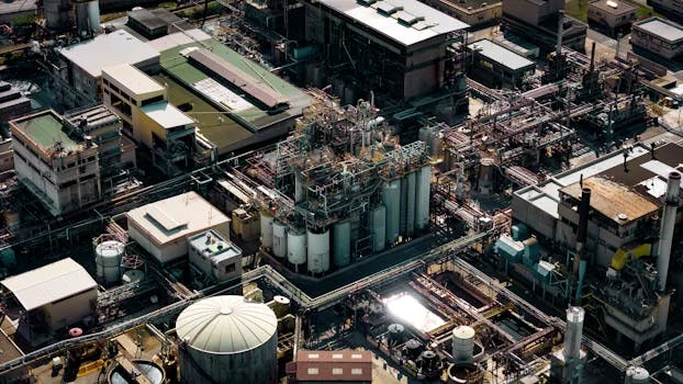
Automated dosing follows a five-step sequence that keeps the process near set point while limiting chemical waste. Each milliliter injected should map to a measured error and a verified effluent response.
Step 1: Detection and Signal Transmission
Work starts at the influent line. A pH probe or turbidity meter reads raw water. If influent shows pH 6.8 and turbidity 250 NTU, the sensor converts those values to a 4–20 mA or digital bus signal and sends it to the PLC.
Step 2: Algorithmic Calculation
The PLC compares live data with setpoints, such as a target pH of 7.2. PID logic computes the error and the dose needed—for example 50 mg/L NaOH—scaled to the current process flow.
Step 3: Precision Dosing Execution
The PLC commands the pump VFD or stepper motor. At 10 m³/h influent flow, the pump may inject 2 L/h of reagent. Diaphragm units change stroke length or frequency; peristaltic units change rotational speed.
Step 4: Rapid Mixing and Reaction
In-line static mixers create turbulence so the chemical blends within about 10 seconds of injection. For coagulants, that mixing window is what lets how PAM dosing systems achieve 95%+ flocculation efficiency before clarification.
Step 5: Feedback and Dynamic Optimization
A downstream sensor checks the result, such as pH 7.1. If the reading sits ±0.3 pH units off target, the PLC trims pump speed. The loop repeats continuously so sudden influent spikes do not break permit compliance.
Process Flow Summary: Raw Influent → Sensor Detection → PLC Signal Processing → VFD Pump Control → Chemical Injection → Static Mixing → Effluent Feedback → PID Adjustment.
Dosing System Efficiency: Real-World Performance Data and Benchmarks
Procurement teams need hard numbers for chemical, labor, and energy savings. Moving from manual or timer-based feed to true closed-loop control is where most plants recover cost.
Manual dosing often fluctuates by 10–20%, while peristaltic pumps hold ±0.5% accuracy (HydropureWater field data, 2025). A textile plant in Vietnam cut coagulant and flocculant use by 20–30% after automation. Chemical cost frequently reaches about 40% of wastewater operating spend, so that reduction dominates ROI.
With PAM dosed ahead of dissolved air flotation, plants commonly reach 92–97% TSS removal and 95%+ flocculation efficiency under stable influent conditions. That process performance sits above the federal secondary-treatment floor of ≥85% SS removal and ≤30 mg/L SS on a 30-day average for POTWs under 40 CFR Part 133. Peristaltic pumps also use about 30% less energy than diaphragm pumps in low-flow, high-precision duty, typically 0.1–0.5 kWh per 1,000 liters dosed.
| Performance Metric | Manual Dosing | Automated Dosing (PLC) | Efficiency Gain |
|---|---|---|---|
| Dosing Accuracy | ±15% to 20% | ±0.5% to 1.0% | ~95% Improvement |
| Chemical Waste | High (Over-dosing) | Minimal (Target-dosing) | 20–30% Cost Savings |
| TSS Removal (with DAF) | 70–80% | 92–97% | Compliance Security |
| Labor Requirement | 2–4 hours/shift | 0.5 hours/day (check) | 80% Labor Reduction |
| Maintenance Cost | Variable | $0.05–$0.15 / m³ treated | Predictable OpEx |
What Is the Best Chemical Dosing Equipment?
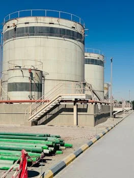
The best chemical dosing equipment for water treatment plants is the pump and control package matched to viscosity, pressure, and closed-loop sensors—not a single universal model. A standard diaphragm pump on high-viscosity polymer will clog; an open-loop timer on variable influent will over-dose.
1. Define objectives and chemical properties. State whether the duty is pH correction, disinfection, or coagulation, then check viscosity and corrosivity. on-site ClO₂ generation for disinfection dosing needs oxidation-resistant materials. Thick PAM usually needs progressive cavity or heavy-duty peristaltic heads.
2. Calculate flow and dosing range. Use: Pump Flow (L/h) = [Influent Flow (m³/h) × Dosage (mg/L)] / [Chemical Concentration (g/L)]. Keep the selected pump near mid-curve for wear life and accuracy.
3. Select the control strategy. Multi-chemical trains (coagulant, flocculant, and pH together) need a PLC skid. Simple single-parameter pH hold can use a standalone PID controller. See polymer dosing system engineering specs and cost optimization strategies for multi-stage layouts.
| Selection Factor | Peristaltic System | Diaphragm System | Progressive Cavity |
|---|---|---|---|
| Best For | Abrasive/Viscous/Gaseous | High Pressure/General use | Very High Viscosity (PAM) |
| Chemical Types | Hypochlorite, Polymers | Acids, Bases, Alum | Thick Sludge, Emulsions |
| Max Accuracy | ±0.5% | ±1% | ±2% |
| Maintenance | Low (Tube replacement) | Moderate (Diaphragm/Valves) | High (Rotor/Stator) |
How Do Dosing Systems Cut Boiler Wastewater?
Chemical dosing systems for boiler feedwater reduce wastewater when antiscalant, oxygen scavenger, and pH control hold cycles of concentration without scale or corrosion trips. Accurate closed-loop feed limits blowdown volume because operators no longer over-treat “for safety.” Plants still must size injection points, quench, and neutralization so concentrated blowdown meets sewer or NPDES limits before discharge.
Common Chemical Dosing Challenges and How to Solve Them
Harsh chemistries still create downtime if suction design, injection spacing, and sensor hygiene are ignored. Most failures trace to air locks, precipitation, or fouled probes rather than PLC faults.
Inconsistent dosing and air locks: Sodium hypochlorite can liberate gas and cause loss of prime. Fit air bleed valves and keep suction lines short. If accuracy drifts, inspect injection nozzles and calibrate sensors weekly to hold ±0.01 pH.
Chemical precipitation: Ferric chloride and lime dosed too close together form solids that plug lines. Space injection points and use static mixers for rapid dilution. Antiscalant dosing or smooth-bore PVDF piping reduces scale on long runs.
Sensor fouling: Biofilm or oil coats pH probes in wastewater and slows response. Ultrasonic cleaners or water-jet sprays extend probe life. In high-solids streams, non-contact ultrasonic flow meters avoid abrasive wear on wetted parts.
Selection checklist: (1) jar-test dosage in mg/L at design flow; (2) confirm pump type vs viscosity and gas content; (3) size tanks for 3–5 days supply; (4) verify containment against 40 CFR § 264.193 where it applies; (5) choose PLC vs standalone PID by number of loops; (6) plan weekly sensor and monthly draw-down checks; (7) reserve spare tubing or diaphragms for the lead pump.
Who this is for: plant engineers and EPC teams specifying coagulants, pH control, or disinfection on industrial or municipal trains. Who should look elsewhere: labs needing only syringe pumps, or sites without chemical storage permits. Next step: share influent flow, target dose, and viscosity so an Automatic Chemical Dosing System can be sized mid-curve.
Frequently Asked Questions
What is the most accurate dosing pump for industrial use?
Peristaltic pumps are generally the most accurate industrial option at ±0.5% of set point. They handle shear-sensitive polymers and fluids with trapped gas without vapor lock. Where discharge pressure is high, stepper-driven diaphragm pumps still reach about ±1% accuracy if sized mid-curve and calibrated on a draw-down test.
How do I set the correct wastewater chemical dosage?
Jar testing sets the starting dosage in mg/L by simulating coagulation and flocculation at several concentrations. The PLC then uses that setpoint and scales pump output in L/h from live influent flow. Re-check jar tests when influent COD, TSS, or temperature shifts enough to change floc size or settling rate.
Can one dosing system handle multiple chemicals?
One pump handles one chemical, but a skid can mount several pumps and tanks under one PLC. That layout sequences pH adjustment before coagulant addition so each reaction runs at its setpoint. Coordinated dosing is standard ahead of clarification steps such as how DAF units remove 95%+ of suspended solids when paired with chemical dosing.
How often should a chemical dosing system be calibrated?
For compliance loops, calibrate pH and ORP sensors weekly with fresh buffer solutions. Run a monthly draw-down test on each pump so delivered volume matches the PLC output after tubing or diaphragm wear. Increase frequency after chemical changeovers or when effluent drift exceeds the control band.