Separate the Data Center Wastewater Streams Before Sizing Equipment
A Gorakhpur data center needs separate treatment trains for domestic sewage, DG cooling and humidification bleed, make-up-water RO reject, and cooling tower blowdown (CTBD); blending them before characterization can overload upstream equipment and foul membranes. CTBD is often the largest recoverable stream, but its dissolved solids and treatment chemicals change the required pretreatment. The process should therefore follow source segregation, equalization or side-stream filtration, stream-specific pretreatment, biological treatment or reverse osmosis (RO), reuse or discharge, and solids handling. For CTBD, the initial chemical screen should cover the reported 1,200–6,000 mg/L TDS range and approximately 4–8 times make-up-water concentration, while final Gorakhpur design values remain subject to site testing (Genesis Water Technologies, 2026).
Domestic sewage requires a biological and solids-removal design because it receives restroom, pantry and kitchen flows. DG cooling and humidification bleed requires separate oil and grease control; an oil slug must not reach UF or RO. Make-up-water RO reject is already a concentrated membrane stream and needs its own flow, chemistry and destination. CTBD requires the most careful scaling assessment because it carries concentrated cooling chemicals and sparingly soluble salts.
Before selecting equipment, request dry-weather and wet-weather samples, hourly and daily flow profiles, source-water quality, cooling chemical inventory, operating hours and measured CTBD flows. Also confirm municipal or groundwater availability, the intended reuse destination, discharge route, temperature constraints and the applicable consent conditions. These inputs—not a generic data-center treatment template—should determine the Gorakhpur process train.
| Stream | Principal contaminants or risks | Required pre-treatment decision |
|---|---|---|
| Domestic sewage | Organic load, suspended solids, nutrients | Flow-profile review; biological treatment and solids handling |
| DG cooling and humidification bleed | Intermittent oil and grease | Isolate and oil removal before equalization or blending |
| Make-up-water RO reject | Concentrated dissolved salts | Separate collection; assess blending or dedicated treatment |
| Cooling tower blowdown | TDS, silica, calcium carbonate, calcium sulfate, residual chemicals | Side-stream filtration, scaling assessment, UF and RO as indicated |
Build the Water Balance and Verify the Reuse Opportunity
Cooling-tower recovery decisions should be based on measured water consumption and a verified mass balance, not on total intake alone. Meter make-up water, blowdown, evaporation, discharge and water retained in products or processes. Water usage and water consumption are not interchangeable: evaporation and product retention remove water from the site, while a treated and reused stream remains within the operating boundary.
The blowdown ratio is 1/(CoC−1). At 4 cycles of concentration (CoC), blowdown is 25% of make-up volume; at 6 CoC, it is 20%. The change is therefore a 20% reduction in blowdown volume, not a 50% reduction, as explained by Genesis Water Technologies (2026). A higher CoC can reduce freshwater demand, but it also raises scaling, corrosion and biological-control demands. The cooling chemistry program and pretreatment must therefore support the proposed operating point before it is adopted.
Scale is not a substitute for measurement. IDE-Tech (2026) reports that a 100 MW evaporative-cooling facility can use up to 2 million litres of water per day. That is a facility-scale reference, not a Gorakhpur design flow. Establish the local baseline through calibrated meters, operating logs and an extended campaign that captures variations in ambient conditions and cooling load.
| Water-balance item | Measurement required | Design use |
|---|---|---|
| Make-up water | Continuous total flow and source | Calculates net withdrawal and candidate reuse demand |
| CTBD | Continuous flow, including operational dumps | Defines treatment capacity and recovery target |
| Evaporation | Estimated from water balance and cooling-system data | Separates consumption from recirculating water |
| Discharge and reuse | Destination, duration and measured quality | Sets consent and concentrate-management constraints |
Protect UF and RO from Scaling, Fouling and Chemical Upsets
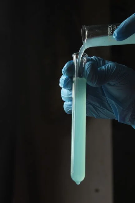
CTBD pretreatment should be designed around the concentrated water entering the membrane system, not the average make-up-water analysis. Genesis Water Technologies (2026) recommends side-stream filtration at 1–5% of circulation flow using 10–25 µm self-cleaning screens. The objective is to remove suspended material before it reaches UF and to prevent cooling-side solids from entering the recovery train.
UF should provide a defined barrier against colloids and suspended solids before RO. The cited UF pretreatment for CTBD and RO feed protection uses 0.01–0.1 µm pore size, 10–30 psi operating pressure, 90–95% recovery and CIP every 1–3 months (HydropureWater’s Kolkata 2026 guide). The final specification must confirm the actual feed condition, flux requirement, backwash arrangement and cleaning chemistry.
Keep DG oil and grease out of the membrane feed. The DAF unit for oily wastewater pretreatment should operate before DG drainage is equalized or blended. A multi-media filter for controlled solids removal can then protect downstream equipment where the analysis supports it. The automatic chemical dosing system should respond to measured feed conditions rather than a fixed nominal dose.
Screen the worst-case top-of-cycle concentrate for silica, calcium carbonate, calcium sulfate, conductivity, pH, turbidity, suspended solids, residual treatment chemicals and antiscalant compatibility. The antiscalant and biocide program must be checked for membrane compatibility, and any biocide entering the recovery train requires review because it can damage UF components or change membrane oxidation conditions.
Monitor conductivity, pH, turbidity and silica at the relevant feed and permeate points. Automatic control should follow measured conditions, while the chemical inventory remains traceable through operating logs. Where CTBD and make-up-water RO reject are considered for joint treatment, their combined chemistry—not either source alone—must set the scaling basis.
| Control point | Minimum design action | Evidence needed for Gorakhpur |
|---|---|---|
| Cooling side-stream | Screen or filter 1–5% of circulation flow | Circulation rate, solids profile and screen performance data |
| DG drainage | Oil removal before equalization | Oil and grease concentrations and event frequency |
| UF feed | Turbidity, suspended-solids and backwash control | Feed chemistry and operating-hour profile |
| RO feed and concentrate | Scaling, fouling and antiscalant control | Worst-case CoC chemistry, silica and saturation data |
Choose a Recovery Route Without Creating a Scaling Trap
Conventional brackish-water RO should be the baseline comparison, but its recovery limit must be stated clearly. IDE-Tech (2026) reports that conventional CTBD treatment typically plateaus at 75–80% recovery before scaling becomes unmanageable. For cooling make-up reuse, permeate quality and recovery are separate questions: suitable permeate does not eliminate the need to treat, discharge or further concentrate the reject.
A high-recovery architecture changes the order of operations. The CTBD first passes through conservative local RO. Its concentrate enters a fluidized-bed reactor where antiscalant is deactivated and sparingly soluble salts precipitate onto seed material as compact pellets. After those salts are removed, the remaining brine can proceed to further RO. This sequence separates salt removal from the osmotic-pressure limit that constrains conventional RO.
IDE-Tech (2026) reports an industrial application operating at around 95% overall recovery with approximately 1 mg/L silica in the permeate. This is an application result, not a guaranteed Gorakhpur output. HydropureWater’s Kolkata 2026 guide also warns that a first-pass design without explicit salt removal should not be quoted above 70% recovery in a consent application. The final recovery guarantee must therefore match the selected architecture and its concentrate route.
Dynamic RO, using short production periods and high-velocity flushing, is an advanced stability measure rather than a default specification. It requires pilot evidence, operating controls and a defined concentrate-management route. The industrial RO system for cooling make-up reuse should be evaluated around this complete train, not as an isolated vessel. Available RO and UF membrane elements for the duty must also be matched to the proven feed chemistry.
| Route | Recovery architecture | Principal limitation |
|---|---|---|
| Conventional brackish-water RO | Filtration, UF, RO and controlled concentrate disposal | Concentrate remains comparatively large and scaling-prone |
| High-recovery RO | Conservative RO, fluidized-bed salt precipitation and further RO | Requires solids handling, chemical control and pilot validation |
| Permeate reuse | RO permeate returned as cooling make-up | Residual brine still requires an approved destination |
Match the End-Use to Sewer Discharge, Partial ZLD or Full Recovery
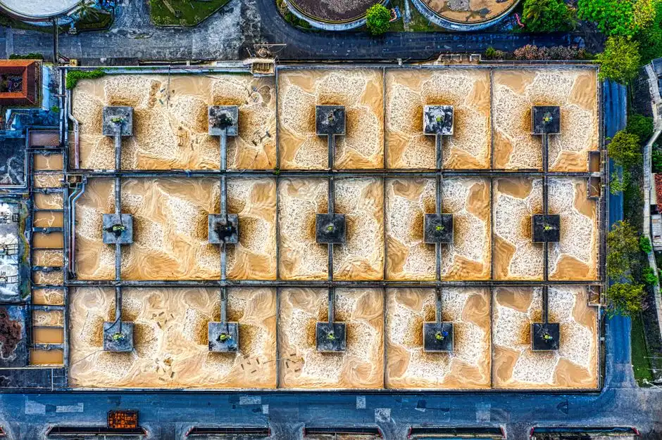
The permitted destination must determine whether treatment is optimized for reuse, sewer discharge or concentrate management. Four routes require separate evaluation: cooling make-up reuse, lower-grade process reuse, treated discharge to a receiving system, and concentrate reduction or zero-liquid-discharge treatment. A reusable permeate does not justify assuming that its concentrate can also be discharged.
HydropureWater’s Kolkata 2026 guide provides a directional global benchmark of US$1.50–3.00 per thousand gallons for a 50,000 GPD RO make-up block. It is not an Indian or Gorakhpur quotation. The same source places full ZLD at US$3–8 million capital expenditure and US$5–15 per thousand gallons operating expenditure. These figures frame capital and operating-cost exposure only; an India-specific estimate requires local equipment quotations, energy tariffs, labour, membrane logistics, chemical consumption and disposal arrangements.
Partial ZLD is relevant when concentrate volume must be reduced without committing to full ZLD. The cited Kolkata framework reports 80–90% RO-concentrate volume reduction through MVC. Full ZLD becomes relevant when consent conditions cap freshwater intake, prohibit discharge or require no liquid discharge; it should not be selected merely because high recovery is technically possible.
For Gorakhpur, verify the receiving route, temperature, TDS, discharge duration, downstream reuse acceptance and local consent conditions before fixing the equipment scope. The regulated data center effluent and discharge guide provides a useful compliance framework, but the applicable local consent must govern the project.
Build the business case on total avoided cost: freshwater, treatment chemicals, energy, discharge fees, concentrate handling and operational risk. Water volume alone will not distinguish a sound reuse project from an uneconomic treatment system.
| End-use or disposal route | What must be demonstrated | Key commercial input |
|---|---|---|
| Cooling make-up reuse | Permeate quality, recovery and residual concentrate route | Freshwater cost and membrane operating demand |
| Lower-grade process reuse | Recipient quality, seasonality and acceptance conditions | Displaced process-water cost |
| Treated discharge | Receiving-system limits and consent | Discharge fees and required polishing |
| Partial or full ZLD | Concentrate volume, salt handling and final residue destination | CAPEX, thermal energy, labour and residue disposal |
Build a Vendor-Ready Equipment and Performance Checklist
Every bid should state design feed flow, hourly and daily variability, the recovery definition, permeate quality, concentrate quality and expected cleaning frequency. “Recovery” must identify the reference stream and system boundary; otherwise a bidder can quote RO recovery while leaving upstream losses and concentrate handling outside the guarantee.
Evaluate UF and RO systems for automatic backwash, PLC control, feed-pressure management, conductivity and silica monitoring, permeate backwash and CIP provisions. Require the controls to show how chemical dosing responds to actual feed chemistry and how an upset triggers isolation or flushing.
For high-recovery or ZLD concepts, require clarification of salt-pellet handling, filtrate return, brine disposal and fouling-control strategy. The plate-and-frame filter press for dewatering salt and clarifier solids should be matched to expected solids generation, cake handling and filtrate return. The treatment valves, filter media and support parts should be specified for compatibility with the confirmed chemistry.
Genesis Water Technologies (2026) describes modular blowdown-treatment systems at 100–300 GPM as a market reference. Actual capacity must follow measured Gorakhpur flows and operating hours. Require FAT and SAT criteria, membrane warranty terms, replacement assumptions, spare-parts availability and local commissioning support.
Include a site-specific pilot or extended analytical campaign before final commitment. Source-water chemistry, cooling operations and the chemical program determine scaling and fouling behavior; a one-off laboratory result is not enough to guarantee plant performance.
| Bid item | Required response |
|---|---|
| Design basis | Measured flow, water chemistry, operating hours and recovery boundary |
| Performance | Permeate, concentrate, recovery, cleaning frequency and deviation response |
| Controls | PLC logic, monitoring, automatic dosing, flushing and CIP |
| Solids handling | Mass balance, dewatering, cake removal and filtrate return |
| Commercial support | Delivery, installation, commissioning, warranty and local spares |
Frequently Asked Questions
What wastewater and cooling blowdown treatment does a data center in Gorakhpur need?
It needs segregated treatment for domestic sewage, oily DG cooling and humidification bleed, make-up-water RO reject, and CTBD. The CTBD train normally requires source characterization, side-stream filtration, scaling control, UF where justified, and RO if cooling make-up reuse is selected. Sewage needs biological treatment; oily DG drainage needs oil removal; RO reject and CTBD need separate concentrate-management decisions. No Gorakhpur equipment capacity should be fixed without measured flows, source-water analysis, cooling chemistry and reuse or discharge conditions.
How much would CTBD treatment cost in Gorakhpur?
A defensible price requires an India-specific quotation rather than a global benchmark. HydropureWater’s Kolkata 2026 guide cites US$1.50–3.00 per thousand gallons for a 50,000 GPD RO make-up block and US$3–8 million capital expenditure plus US$5–15 per thousand gallons operating expenditure for full ZLD; those are directional global figures, not Gorakhpur prices. Request a split quotation for pretreatment, RO, concentrate treatment, controls, energy, chemicals, solids handling, installation and commissioning. Also ask for sensitivity cases at different recovery, reuse and disposal assumptions.
What determines the required CTBD treatment capacity?
CTBD capacity depends on cooling-system operation, make-up volume, cycles of concentration, evaporation, measured blowdown, operating hours and the selected recovery route. Facility MW alone is not enough. IDE-Tech (2026) cites up to 2 million litres per day for a 100 MW evaporative-cooling facility, but this must not be applied directly to the proposed Gorakhpur campus. Size the plant from a measured baseline and include daily and seasonal peaks.
How should a CTBD treatment supplier be selected?
Compare suppliers on guaranteed recovery, permeate and concentrate quality, scaling-control evidence, automatic monitoring, cleaning design, service support and solids handling—not purchase price alone. Require a pilot based on the actual CTBD chemistry, FAT and SAT criteria, membrane warranty terms, replacement assumptions, spare-parts availability and local commissioning support. For high-recovery bids, ask the supplier to document the complete salt-precipitation and residual-brine route.
What compliance information is needed before selecting reuse or ZLD?
Confirm the applicable consent, receiving-system limits, freshwater conditions, reuse destination, temperature limits, TDS requirement, discharge duration and downstream acceptance before fixing the final scope. Do not transfer regulatory limits from another Indian city into the Gorakhpur design basis. Submit the proposed discharge and reuse concept for confirmation, then size the treatment train against those conditions. If discharge is restricted or freshwater intake is capped, evaluate partial or full ZLD against the actual consent and concentrate destination.