
Choose DAF or a Full ETP for a Berlin Factory
A Berlin factory requires a DAF system when wastewater contains oil, grease, suspended solids, or colloidal material that must be removed before discharge or further treatment; a full ETP is necessary when the process requires primary, biological, or tertiary treatment stages. DAF uses recirculated, compressed air to form microbubbles that lift contaminants for skimming, while a full ETP adds equalization, chemical reaction, clarification, and biological stages. The correct choice depends on representative wastewater tests, peak flow, required effluent quality, reuse plans, and local Berlin discharge conditions.
DAF is a physico-chemical separation process: small air bubbles attach to suspended particles and oil droplets, increasing their flotation rate so a skimmer can remove the floating material. It is a focused option for the physical removal of suspended solids, FOG, oil, and colloidal matter. ETP configurations generally include three broad levels: primary physical and chemical treatment, secondary biological treatment, and tertiary treatment before final release. If the Berlin industrial wastewater requires biological treatment or final polishing, a DAF-only package will not cover the full duty.
The decision should follow the wastewater characteristics rather than a product name. Evaluate the wastewater profile, peak flow, treatment objective, reuse plans, and available footprint. Berlin compliance must be checked against the factory’s actual discharge route and applicable local requirements; the supplied research does not establish a universal Berlin effluent limit.
| Decision point | Indicates a DAF-led scope | Indicates a broader ETP scope |
|---|---|---|
| Primary objective | Remove suspended solids, oil, grease and colloidal material | Add biological treatment or final polishing |
| Wastewater route | Sewer pretreatment or further treatment on site | Site-specific final discharge or reuse |
| Treatment train | Equalization, chemical reaction, clarification and flotation | Primary, secondary and possibly tertiary stages |
| Key design inputs | Oil character, solids, flow and skimming duty | Same inputs plus biodegradability and effluent targets |
For a comparison of equipment scope, engineering constraints, and cost decisions, use the 2026 DAF unit engineering and cost decision framework.
Characterize the Wastewater Before Sizing Equipment
A credible DAF or ETP proposal cannot be sized from average flow and catalogue capacity alone. The buyer must provide representative wastewater data, operating variability, and a defined treatment outcome before suppliers compare solutions.
Request samples across normal production, peak production, cleaning cycles, and batch discharges. A single laboratory result can miss intermittent emulsions, concentrated wash water, or high-solids discharges. The process sequence starts with equalization to balance flow and load, followed by a reaction tank for coagulant, caustic soda, and flocculant dosing, and then clarification. These functions determine whether the selected flotation or biological stage receives a stable and appropriate feed.
Provide average and peak flow, operating shifts, storm or wash-water inputs, and expected production changes. Test suspended solids, oil and grease, free versus emulsified oil, pH, and COD, plus contaminants specific to the factory sector. These are relevant process parameters, though specific sampling frequencies or acceptance limits must be established against the actual discharge route, permit conditions, and reuse application.
State whether the objective is direct discharge, pretreatment to a sewer, reuse within the factory, or compliance with a site-specific permit. For reuse, identify the receiving process and required water quality; “treated water” is not a sufficient specification.
| Information to request | Why it affects selection | Minimum decision use |
|---|---|---|
| Representative analysis | Defines contaminant load and treatment difficulty | Separate process and target water quality |
| Flow profile | Sets equalization and equipment capacity duties | Average, peak and operating duration |
| Oil and solids form | Influences chemical reaction and flotation performance | Free versus emulsified oil; suspended solids |
| pH and COD | Tests chemical demand and biological treatment suitability | Normal and batch-discharge results |
| Discharge or reuse route | Defines the required performance basis | Receiving authority, permit and reuse process requirements |
HydropureWater’s DAF catalogue spans 4–300 m³/h across 13 standard models, but that is a catalogue range, not a site-specific sizing result. A PLC-controlled chemical dosing system may be required, but its chemical capacity and control strategy depend on the wastewater analysis and treatment sequence.
Build the Right Treatment Process Flow
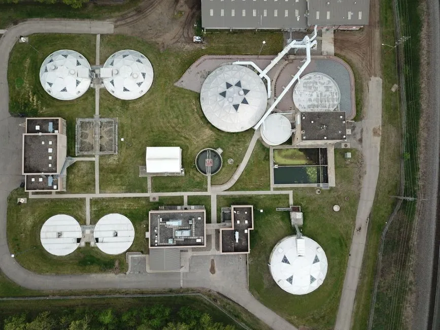
A defensible treatment train separates flow and load balancing, chemical conditioning, solids separation, flotation, biological treatment, and final storage or polishing. The standard sequence includes an equalization tank, reaction tank, clarifier, buffer tank, DAF, oil and sludge drums, and process-water storage.
- Equalization tank: balances variable flow and contaminant load before treatment.
- Reaction tank: supports pH adjustment and floc formation through coagulant, caustic soda, and flocculant.
- Clarifier or clarifier drum: settles solids and separates concentrated sludge from clarified water.
- Buffer tank: stores clarified water temporarily and smooths flow into the DAF.
- DAF: removes remaining suspended solids, oil, and grease; polyelectrolyte dosing supports flotation.
- Oil and sludge collection: directs floated oil and separated sludge to drums or another specified management route.
The DAF installation includes a recirculation pump, compressor, polyelectrolyte dosing, and skimmer. Pressurized, air-saturated recycle water returns to the flotation tank; the pressure drop releases microbubbles typically 10–100 microns in diameter. These bubbles attach to suspended solids and small oil droplets, which rise and are removed by a mechanical skimmer.
DAF should be placed according to the wastewater objective, not treated as a universal ETP. In refinery-type wastewater, DAF can protect downstream biological treatment by removing emulsified oil and fine solids before they reach the biological reactor. Add biological treatment only where the wastewater and treatment objective require it.
| Process stage | Function in the treatment train | Scope item to verify |
|---|---|---|
| Equalization | Balances flow and load | Working volume and mixing |
| Reaction | pH adjustment and floc formation | Chemical storage, dosing and control |
| Clarification | Settles solids | Sludge withdrawal and access |
| DAF | Flotation of remaining solids, oil and grease | Recirculation, compression, dosing and skimming |
| Biological treatment | Removes biodegradable dissolved organics where required | Process basis and downstream protection |
| Storage or polishing | Supports reuse or final discharge | Water quality and final destination |
Include residue handling in the conceptual scope. A skimmer removes a concentrated floating layer, and clarifiers produce sludge; DAF is not a zero-residue process. The supplier should specify collection, storage, dewatering, or disposal interfaces. A high-efficiency sedimentation tank may be relevant where clarification is required alongside the industrial dissolved air flotation system.
Match the Treatment Scope to the Factory's Objective
The correct package depends on what the factory must remove and where the water goes next. A DAF system, chemical dosing, and sludge dewatering are separate functions; their inclusion should follow from the wastewater analysis and the required solids, FOG, and oil-removal performance.
For a broader flow requiring biological treatment, an MBR option may be appropriate if its treatment objective and capacity match the wastewater. HydropureWater lists 10–2,000 m³/day and filtration below 1 μm for its MBR product, but those figures are catalogue parameters, not proof of suitability for a Berlin factory.
For clarification-intensive treatment, a lamella clarifier is a compact option. Supplied product data gives surface loading rates of 20–40 m/h and chemical consumption reduction of up to 30%; the exact scope must be verified during design. The integrated MBR wastewater treatment option and lamella clarification solve different process duties, so a plant may require one, both, or neither.
For a compact multi-stage clarification and filtration duty, the JY series offers a capacity range of 10–200 m³/h. Its design focuses on coagulation, flocculation, sedimentation, filtration, and backwash. It should be compared against DAF where oil and FOG removal dominate, rather than treated as an interchangeable label for every factory effluent treatment plant.
| Factory objective | Potential equipment scope | Evidence-based limitation |
|---|---|---|
| Suspended-solids and FOG removal | DAF, chemical dosing and sludge handling | Selection requires representative analysis and flow data |
| Biological treatment requirement | MBR-based option where appropriate | Listed capacity is 10–2,000 m³/day |
| Clarification-intensive duty | Lamella clarifier | Listed surface loading is 20–40 m/h; reduction is stated as up to 30% |
| Clarification plus filtration | JY integrated series | Listed capacity is 10–200 m³/h |
| Wastewater reuse | Storage and treatment matched to the receiving process | S1 permits storage for reuse, but reuse quality must be confirmed |
Clarified water may be stored for reuse or final discharge, but this is a process route, not proof of reuse feasibility. Confirm water quality, receiving-process requirements, and the applicable Berlin discharge or reuse conditions. No listed configuration automatically satisfies Berlin discharge, trade-effluent, or reuse requirements. If sludge dewatering is part of the scope, define the interface with a plate-frame filter press and the required cake-handling route.
Turn the Requirement Into a Supplier Brief
Comparable quotations require the same wastewater basis, treatment objective, and scope boundary. A useful enquiry includes the wastewater analysis, average and peak flow, operating hours, production profile, target effluent or reuse quality, available footprint, utilities, and future expansion. It should also state the discharge route and the permit assumptions to be checked against applicable Berlin requirements.
Ask each bidder to identify every tank, pump, compressor, dosing unit, skimmer, sludge-collection route, control component, and utility connection. Request the process flow, mass-balance basis, solids-loading calculation, chemical-consumption estimate, equipment-sizing calculations, utility demand, control narrative, commissioning plan, and O&M assumptions. A unit price without this information cannot be compared reliably.
| Supplier deliverable | Decision check | Why it matters |
|---|---|---|
| Process flow and equipment list | Does the scope cover the complete treatment objective? | Excludes hidden omissions and duplicated equipment |
| Sizing and mass balance | Are flow, load and chemicals linked to the wastewater data? | Tests whether the proposal is engineered rather than selected from a catalogue |
| Performance basis | Are test methods, guarantee conditions and exclusions stated? | Allows like-for-like comparison |
| Utilities and controls | Are power, compressed air, chemicals and control interfaces defined? | Reveals installation and operating requirements |
| Sludge and commissioning | Are residue routes, testing and handover defined? | Closes the gap between equipment delivery and operation |
Flag compliance risk when a proposal omits authorization review, discharge-route analysis, sample data, or evidence that the process fits the actual wastewater. Use the 2026 DAF unit engineering and cost decision framework for deeper engineering and cost review. The industrial DAF treatment configuration guide can support discussion of equipment arrangement, but neither substitutes for site data or Berlin-specific review.
Frequently Asked Questions
How should a Berlin factory size an industrial DAF or ETP?
Start with representative wastewater analysis, average and peak flow, operating profile, treatment objective, and reuse or discharge requirements. HydropureWater’s DAF catalogue spans 4–300 m³/h across 13 standard models, but that range is not a sizing calculation. The selected model and treatment train must be checked against the factory’s actual contaminant load, peak demand, and performance basis.
How do I compare DAF and ETP suppliers fairly?
Require each bidder
Frequently Asked Questions
What size DAF system does a Berlin factory with 25 m³/h wastewater need?
For a continuous flow of 25 m³/h, a Dissolved Air Flotation (DAF) system should be sized with a hydraulic loading rate typically between 5 and 10 m³/m²/h. This requires a clarification surface area of at least 2.5 to 5 square meters, though a safety margin is recommended to account for peak flow variations and peak solids loading.
You must also ensure the system includes a pressurized recycle pump capable of saturating 5-10% of the total flow with air to achieve the required micro-bubble formation. For a 25 m³/h capacity, a system with a footprint of approximately 15-20 square meters, including the flotation tank, saturation vessel, and sludge removal mechanism, is standard for industrial applications.
How much does an industrial ETP or DAF system cost for a factory in Germany?
The capital expenditure for a turnkey industrial DAF system in Germany typically ranges from 80,000 EUR to 250,000 EUR, depending on the material of construction (AISI 304 or 316L stainless steel) and the level of automation. A complete modular Effluent Treatment Plant (ETP), including chemical dosing, pH adjustment, and sludge dewatering, can range from 200,000 EUR to over 600,000 EUR.
Operational costs must also be factored in, including electricity consumption for compressors, polymer and coagulant chemicals, and sludge disposal fees, which in the Berlin/Brandenburg region are governed by local waste disposal regulations and typically range from 150 to 300 EUR per ton of dewatered sludge.
What information should I request when comparing industrial wastewater equipment suppliers?
When evaluating suppliers, request a detailed process flow diagram (PFD) and a mass balance calculation that accounts for your specific influent COD, BOD, TSS, and FOG (Fats, Oils, and Grease) levels. You should also demand a performance guarantee based on the specific discharge parameters required by Berlin water authorities (Senatsverwaltung für Umwelt).
Additionally, ask for the technical specifications of the saturation system, the expected sludge dryness percentage (typically 15-25% for DAF systems), and the availability of local German-speaking service technicians. Ensure the quote includes compliance with DIN EN 12255 standards for wastewater treatment plants.
Can DAF alone provide compliant wastewater for reuse in a Berlin factory?
A DAF system is primarily a physical-chemical separation process designed to remove suspended solids, emulsified oils, and some colloidal matter. While it is highly effective at reducing TSS and FOG, it generally cannot achieve the low BOD, nitrogen, and phosphorus levels required for full industrial water reuse without secondary biological treatment.
To reach standards suitable for process water reuse, DAF is typically used as a pretreatment step followed by a Membrane Bioreactor (MBR) or Reverse Osmosis (RO) system. Relying on DAF alone is rarely sufficient for compliance with the strict indirect discharge limits or reuse quality standards mandated by the Berlin Senat.
How long does it take to deliver and commission an industrial DAF system in Germany?
The standard lead time for an industrial DAF unit in Germany is 16 to 24 weeks from the date of order, depending on the complexity of the integrated control systems and the availability of stainless steel components. This timeframe includes engineering design, manufacturing, and factory acceptance testing (FAT).
On-site installation and commissioning usually require an additional 2 to 4 weeks. This period covers mechanical assembly, electrical integration into the factory's PLC/SCADA network, and the crucial optimization phase, where chemical dosing ratios are calibrated to ensure the effluent meets local regulatory compliance before full-scale operation begins.