
How a DAF System Treats Oily Wastewater
A dissolved air flotation (DAF) system for oily wastewater removes suspended oil and grease by saturating a pressurized recycle stream with air and then releasing it at atmospheric pressure inside a flotation tank, generating micro-bubbles that attach to oil droplets and float them to the surface for skimming. According to the Wikipedia entry on dissolved air flotation, a portion of clarified effluent is pumped into a pressure vessel (the air drum) where compressed air dissolves into it, and that saturated stream is recycled through a pressure reduction valve at the front of the float tank, where the air comes out of solution as tiny bubbles that nucleate on suspended particles and lift them into a surface froth removed by a skimmer (Wikipedia, "Dissolved air flotation").
The technique is widely deployed in petroleum refineries, petrochemical and chemical plants, natural gas processing, paper mills, and general industrial water treatment (Wikipedia). The feed water is often dosed with a coagulant such as ferric chloride or aluminum sulfate and/or a flocculant so colloidal and emulsified oil report to the float layer rather than staying dispersed (Wikipedia).
The form of the oil governs whether DAF alone is sufficient. Energy Sources identifies three oil forms present in industrial wastewater — free floating oil, an unstable oil/water emulsion, and a highly stable oil/water emulsion — sourced from petroleum refineries, bilge and ballast water, workshops, petrol stations, rolling mills, and edible-oil and soap factories (Energy Sources, "Treatment of Oily Wastewater Using Dissolved Air Flotation Technique"). Free oil is readily removed by gravimetric separators and unstable emulsions by mechanical or chemical means, but stable emulsions typically demand chemical coagulation/flocculation ahead of DAF, or a polishing barrier such as ultrafiltration. The HydropureWater DAF system (4–300 m³/h, 13 standard models) is documented for food processing, pulp & paper, textile, metalworking, petrochemical, and municipal pre-treatment duty, which confirms the unit class against the same industrial sources the academic literature cites.
Air vs Nitrogen: The Spec Callout Refinery Buyers Miss
In the oil industry, dissolved gas flotation (DGF) units do not use air as the flotation medium because of the explosion risk — nitrogen is used instead to create the bubbles (Wikipedia, "Dissolved air flotation"). This is a specification line item, not an optional accessory: any refinery, petrochemical, or upstream oil and gas DAF should be written into the purchase order as a DGF with a confirmed nitrogen supply, while food, textile, and metalworking duties typically remain on standard air DAF. The University of the Aegean study on synthetic oily wastewater used air at 72 L/min air flow rate and 10 minutes flotation time, confirming that laboratory and non-hazardous oily DAF duty is validated on air (University of the Aegean, GNEST paper 05451). For procurement, the practical implication is a two-track RFQ: an air DAF for the general-industry stream and a nitrogen DGF for any hydrocarbon-saturated influent, with the nitrogen supply, vapor-space inerting, and instrumentation reflected in the vendor data sheets rather than added later as a modification. The Best DAF unit for industrial wastewater buyer framework covers the same separation in its decision logic.
Tank Geometry, Residence Time and Lamella Packing
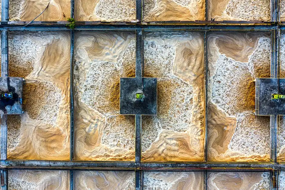
Tank geometry is a sizing decision, not a cosmetic one. Wikipedia states that circular DAF units need only about 3 minutes of residence time and are noted as more efficient, while rectangular DAF units require 20 to 30 minutes, and the circular configuration supports a spiral-scoop skimmer arrangement (Wikipedia, "Dissolved air flotation"). Some DAF designs integrate parallel-plate (lamella) packing to increase effective separation surface area and raise oil-removal efficiency when footprint is constrained (Wikipedia). For oily duty specifically, the University of the Aegean RSM study reported the DAF optimum at 10 minutes flotation time and 72 L/min air flow rate on a synthetic oily wastewater, with downstream MBBR at 23.5 hr HRT and 13/23 min mixing — a useful benchmark for combined DAF + biological polishing trains (University of the Aegean, GNEST 05451). Because the HydropureWater DAF system (4–300 m³/h, 13 standard models) is offered as a catalog line with micro-bubble technology and automatic skimming, the tank-geometry decision reduces to a flow-and-footprint match against the standard models rather than a custom engineering exercise.
| Design variable | Value / range | Source |
|---|---|---|
| Residence time, circular DAF | ~3 minutes | Wikipedia, "Dissolved air flotation" |
| Residence time, rectangular DAF | 20–30 minutes | Wikipedia, "Dissolved air flotation" |
| DAF flotation time (oily, RSM optimum) | 10 min | University of the Aegean, GNEST 05451 |
| DAF air flow rate (oily, RSM optimum) | 72 L/min | University of the Aegean, GNEST 05451 |
| Skimmer arrangement (circular DAF) | Spiral scoop | Wikipedia, "Dissolved air flotation" |
| Packing upgrade for footprint-constrained duty | Parallel-plate (lamella) packing | Wikipedia, "Dissolved air flotation" |
| Standard DAF model band | 4–300 m³/h, 13 standard models, micro-bubble, automatic skimming | HydropureWater DAF product catalog |
Sizing a DAF for Oily Streams: Parameters to Lock In
A vendor quotation is only as good as the inputs behind it. The minimum influent dataset for sizing a DAF on oily duty is the same parameter set the S5 study monitored: oil and grease (O&G), total suspended solids (TSS), chemical oxygen demand (COD), pH, and temperature, classified by oil form — free oil, unstable emulsion, or stable emulsion per the Energy Sources taxonomy (Energy Sources, "Treatment of Oily Wastewater Using Dissolved Air Flotation Technique"; University of the Aegean, GNEST 05451). The chemistry window matters as much as the hydraulic window: coagulant (ferric chloride or aluminum sulfate) and flocculant selection and dose determine whether emulsified oil attaches to the bubble surface or stays dispersed (Wikipedia, "Dissolved air flotation"). The hydraulic window is target flow in m³/h, peak factor, and allowable hydraulic loading — values that should be mapped to the 4–300 m³/h HydropureWater catalog band to shortlist a standard model before any custom engineering is discussed. The safety window is the air-versus-nitrogen DGF call already covered, plus material of construction for the saturator, skimmer, and wetted parts in oily service, and a downstream sludge-handling plan that links the floated sludge to a plate-and-frame filter press as a probable follow-on. The HydropureWater automatic chemical dosing skid integrates with the DAF for the chemistry window.
| Sizing window | Inputs to lock in before RFQ | Why it matters |
|---|---|---|
| Influent characterization | O&G, TSS, COD, pH, temperature; oil form (free / unstable / stable) | Determines whether DAF alone, DAF + chemistry, or DAF + UF/RO polishing is required (Energy Sources taxonomy; S5 monitoring set) |
| Chemistry window | Coagulant (ferric chloride or aluminum sulfate) and flocculant type and dose | Drives whether emulsified oil reports to the float layer (Wikipedia, "Dissolved air flotation") |
| Hydraulic window | Average and peak flow (m³/h), allowable hydraulic loading | Maps to 4–300 m³/h catalog band; 13 standard models available |
| Safety window | Air vs nitrogen (DGF); wetted-parts material; vapor-space classification | Refinery / petrochemical / O&G duty must specify nitrogen (Wikipedia, DGF note) |
| Sludge window | Float solids yield, downstream dewatering path | Float is the controlling disposal cost; plate-and-frame filter press is the typical follow-on |
The deeper engineering context — including the A/S ratio and recycle-rate selection that flow from these inputs — is covered in the Best DAF unit for industrial wastewater buyer framework.
Where DAF Fits in the Oily-Water Treatment Train
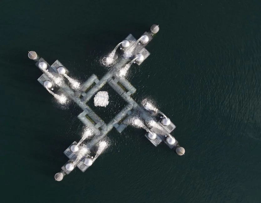
DAF is one node in a train, not a stand-alone purchase. Energy Sources states that free oil is readily removed by gravimetric/API separators and unstable emulsions by mechanical or chemical means — DAF therefore typically sits downstream of an API separator for bulk free-oil removal and upstream of biological or membrane polishing for the emulsified load (Energy Sources, "Treatment of Oily Wastewater Using Dissolved Air Flotation Technique"). Where emulsified oil load is high or discharge limits are tight, the DAF is paired with ultrafiltration as a polishing barrier; the HydropureWater ultrafiltration polishing system is documented for colloid and emulsified-oil removal. For biological polishing, the University of the Aegean RSM work on DAF + MBBR reported measurable reductions in COD, O&G, NH3-N, and TSS on synthetic oily wastewater under optimized conditions, supporting DAF as the primary oil-removal step ahead of an attached-growth biological stage (University of the Aegean, GNEST 05451). On the upstream side, a refinery or rolling-mill scope typically begins with an API oil-water separator; on the downstream side, a biological stage such as the HydropureWater MBR integrated wastewater treatment unit is the common pairing when reuse or tight discharge is the target.
Decision Framework: Choosing DAF for Your Oily Stream
The buying decision collapses to a small number of stream-driven questions. The table below maps stream type to DAF configuration and to the upstream/downstream unit operations the vendor RFQ should reflect; the sizing check is to keep peak flow inside the 4–300 m³/h standard-model band (HydropureWater DAF product catalog) so the unit is a catalog selection rather than a custom build.
| Stream type | DAF configuration | Upstream / downstream |
|---|---|---|
| Refinery, petrochemical, upstream oil & gas oily wastewater | DGF (nitrogen) DAF; standard air is not acceptable | API separator upstream; UF or biological polishing downstream where required |
| Metalworking, rolling mill, compressor-condensate oily wastewater | Standard air DAF with chemical dosing (ferric chloride / alum + flocculant) | UF polishing where water reuse is the target; plate-and-frame press on float |
| Food processing, edible-oil, soap-factory oily wastewater | Standard air DAF; biological polishing per S5 DAF + MBBR reference | Sludge dewatering on the float; possible UF if FOG breakthrough into reuse loop |
| Bilge / ballast, workshop, petrol-station oily wastewater | Air DAF sized to peak flow; chemistry window confirmed against emulsion stability | API or coarse screening upstream; discharge polishing per local limits |
Two comparative reads inform this framework. The DAF vs API separator comparison is the right reference for the upstream boundary, the DAF vs sedimentation comparison for the alternative-primary question, and the DAF oil water separator step-by-step process for the mechanism in detail.
Frequently Asked Questions
What oil removal rate can I expect from a DAF on oily wastewater?
Removal performance is oil-form dependent rather than a single headline number. Per the Energy Sources taxonomy, free oil is readily removed by gravimetric separators, unstable emulsions respond to mechanical or chemical means, and highly stable emulsions typically require chemical coagulation/flocculation ahead of DAF or a polishing step such as ultrafiltration (Energy Sources, "Treatment of Oily Wastewater Using Dissolved Air Flotation Technique"). Request vendor-validated removal data at your actual oil form and influent O&G before committing to a number.
Should I specify a DAF with air or with nitrogen for a refinery application?
Specify DGF with nitrogen. Wikipedia is explicit that in the oil industry dissolved gas flotation units do not use air as the flotation medium due to explosion risk, and nitrogen is used instead to create the bubbles (Wikipedia, "Dissolved air flotation"). This belongs on the purchase-order line item, not as a field retrofit, and the RFQ should call out the nitrogen supply, vapor-space inerting, and instrumentation as part of the scope.
How do I size a DAF for my oily stream without over-specifying a custom unit?
Map your peak flow to the standard-model band first — the HydropureWater DAF line covers 4–300 m³/h across 13 standard models — and only step outside that band if peak flow forces it (HydropureWater DAF product catalog). Pair the flow check with the influent dataset the S5 study monitored (O&G, TSS, COD, pH, temperature) and confirm chemistry window (ferric chloride or aluminum sulfate plus flocculant) so the shortlist reflects real operating conditions, not just hydraulic capacity.
Where does a DAF sit relative to an API separator and to ultrafiltration or RO polishing?
DAF is the primary oil-removal step, not the only one. Energy Sources places gravimetric/API separators upstream for free oil and mechanical/chemical treatment for unstable emulsions, positioning DAF after the API separator and ahead of biological or membrane polishing (Energy Sources, "Treatment of Oily Wastewater Using Dissolved Air Flotation Technique"). The DAF system cost and pricing guide covers how this positioning affects total installed cost, and the inputs a buyer should request from the vendor for each train option.