Why Nashik Data Centers Need a Blowdown Strategy, Not Just a Cooling Tower
Evaporative cooling at typical data centres loses 70–80% of withdrawal to evaporation and 20–30% as blowdown, and even a closed-loop system returns roughly 90–95% of its water as warm wastewater (KETOS). At 4 cycles of concentration, blowdown volume is 25–30% of makeup water; pushing higher cycles lowers that volume but worsens chemistry, because dissolved solids, silica and treatment-chemical residuals all accumulate (Genesis Water Technologies).
The Godavari at Eklahare is documented as polluted enough to affect the local Nashik thermal power station's demineralised and cooling water, so a new hyperscale or colocation facility drawing from the same river must plan for variable source quality rather than assume a published average (World Wide Journals, 2013). India's National Green Tribunal issued notice to MoEFCC in October 2026 on industrial effluent and ZLD rules, which signals tighter consent conditions for new high-volume industrial users, including data centres, than the 2017–2019 consent envelopes were designed for.
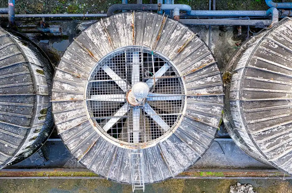
For a Nashik project manager, that translates into three operational realities. First, the cooling tower is the largest single water consumer on the site and the largest single wastewater source; consent conditions will be written around it. Second, the Godavari source is not the stable TDS envelope a textbook assumes, so pretreatment has to be designed around seasonal turbidity and alkalinity swings, not annual averages. Third, designing only for sewer discharge leaves the consent vulnerable to revision if the NGT pressure crystallises into a ZLD mandate for high-volume industrial users. The defensible move is to size the treatment train for cooling-tower makeup reuse now, with concentrate management that can be upgraded to partial or full ZLD within the same footprint if consent conditions tighten.
Nashik Source-Water and Blowdown Quality Envelope
The design envelope for a Nashik data centre reusing cooling-tower blowdown is defined by parameters established for cooling makeup and the blowdown resulting from a 4–6 cycle cooling loop. The targets below come from Genesis Water Technologies' data-centre reuse guidance and apply whether the source is Godavari raw water, municipal supply, or a blend.
| Parameter | Cooling-tower makeup target | Expected blowdown range (4–8× makeup) | Design implication |
|---|---|---|---|
| Total dissolved solids (TDS) | 500–1,500 mg/L | 1,200–6,000 mg/L | RO permeate at 10–50 mg/L blends back into makeup |
| Hardness (as CaCO₃) | <200–400 mg/L | Scales with cycles | Antiscalant + NF or RO for hardness control |
| Suspended solids | <10–25 mg/L | 10–50 mg/L | Spiral side-stream filter at 10–25 µm upstream of UF |
| HPC (heterotrophic plate count) | <10,000 CFU/mL | Higher in basin | UF barrier + biocide programme in loop |
| pH | 6.5–8.5 | Drifts up with cycles | pH trim before RO |
| Alkalinity (as CaCO₃) | 50–200 mg/L | Scales with cycles | Godavari source tends to be elevated; design for it |
With Godavari-quality makeup, expect elevated alkalinity and seasonal turbidity swings; turbidity upstream of large dams in the basin is the variable to design around, not the average value. The academic study of the Godavari at Eklahare, downstream of which several data-centre plots are being marketed, found pollution levels that already force the adjacent thermal power station to run variable-quality pretreatment, and a data centre siting on the same reach should not assume better (World Wide Journals, 2013). The wider India PFAS treatment gaps in 2026 also matter here, because cooling-tower blowdown concentrates whatever comes in with the source water, and Indian consent is moving toward PFAS monitoring even where discharge limits are not yet set.
Where reuse is not possible and the project has to plan a discharge route, Genesis reports direct discharge fees of $5–$15 per 1,000 gal in water-stressed regions and notes that some jurisdictions cap blowdown TDS at <1,500 mg/L, which would prohibit discharge of concentrated blowdown without treatment. Those figures are US-context and should be read as a planning envelope, not a Nashik-specific number — the actual MPCB consent letter is the controlling document, and the buyer should request the consent draft before locking the discharge path.
Treatment Train: Spiral Filtration → UF → RO for Makeup Reuse

The realistic Nashik train for cooling-tower makeup reuse is a three-stage membrane system with side-stream filtration in the cooling loop as the first barrier. This configuration is familiar to Indian EPCs, scales from a 1 MW edge site to a 50–100 MW hyperscale campus, and allows for the addition of MVC evaporation later if consent requirements tighten.
Stage 1 — Side-stream spiral filtration on the cooling loop. Self-cleaning spiral filters at 10–25 µm cut blowdown suspended solids and protect downstream membranes, and are sized at 1–5% of circulation flow (Genesis). Continuous scraping removes captured solids without backwash downtime, which matters for a site that cannot take a cooling loop offline for media change-out. Side-stream filtration also enables higher cycles of concentration by keeping particulates and biofilm fragments out of the basin, which is what produces the blowdown chemistry that downstream membranes can actually handle.
Stage 2 — Ultrafiltration as RO pretreatment. A HydropureWater hollow-fiber UF system at 0.01–0.1 µm pore size removes bacteria, viruses and colloids at 90–95% recovery and is the standard RO/NF pretreatment for blowdown (Genesis). UF operates at low pressure (10–30 psi), tolerates the variable feed that comes off a Godavari-fed cooling loop, and backwashes with permeate, with chemical cleaning every 1–3 months. The UF stage is what makes RO economically viable on blowdown; without it, RO membranes foul on the colloidal and biological load and the OPEX envelope collapses.
Stage 3 — Reverse osmosis (or nanofiltration) for dissolved solids. RO removes 95–99% of TDS and produces 10–50 mg/L permeate suitable for blending back into cooling makeup, with antiscalant dosing required for silica and hardness control (Genesis). Operating pressure sits at 150–400 psi to overcome the osmotic pressure of concentrated blowdown, and recovery is typically 50–85% limited by scaling potential. Where the goal is partial softening rather than full demineralisation — for example, to enable higher cycles of concentration without going to full RO — NF is the lower-pressure option at 75–150 psi with permeate TDS roughly 30–50% of feed, which is enough to bring hardness back inside the 200–400 mg/L as CaCO₃ target without the energy cost of RO.
The choice between RO and NF is driven by consent and economics, not by technology availability. If MPCB consent is for sewer discharge with a TDS cap, NF plus discharge is often enough. If the consent is for makeup reuse with no sewer pathway, or if the NGT pressure pushes the site toward ZLD, RO is the floor and MVC evaporation sits on top of it.
When You Need ZLD or Partial ZLD Instead of Reuse-and-Discharge
Full zero liquid discharge combines RO concentration (70–80% recovery) with mechanical vapour compression (MVC) evaporation at 95–98% on the concentrate, and a crystallizer that turns the remaining brine into a solid salt cake for disposal (Genesis). Overall water recovery reaches 95–99% as a solid waste stream of less than 1% of original blowdown volume. MVC distillate is <10 mg/L TDS, suitable for direct cooling-tower makeup, but uses 15–25 kWh per 1,000 gal of distillate and costs $1–$3 million for 10,000–30,000 GPD systems in the Genesis reference set.
Partial ZLD is the realistic middle ground for most Nashik sites. It concentrates blowdown to reduce discharge volume by 80–90%, captures most of the water-recovery benefit at substantially lower capex than full ZLD, and leaves a small brine stream that can be sent to deep well injection, hauling, or periodic discharge under special permit (Genesis). The decision is consent-driven: if MPCB's draft consent allows sewer discharge at the projected TDS and flow, reuse-and-discharge is the lowest-cost path; if the consent is tight, partial ZLD pre-empts a consent revision mid-project.
Given the October 2026 NGT notice to MoEFCC on industrial effluent and ZLD rules, designers in India should pre-size concentrate management even if the current consent allows sewer discharge, because retrofitting MVC into a built-out data centre hall is a multi-month civils exercise. Pre-sizing means allocating floor space, power, and a crystallizer or brine-haul route now, even if the first year of operation runs the RO into the sewer. The 2026 ZLD adoption trends for India piece tracks the same pressure from the equipment-vendor side, and the buyer should read it alongside the consent draft before finalising the plot plan.
Capex and Opex Ranges an Indian Buyer Should Plan For
The figures below come from Genesis Water Technologies' data-centre reuse reference set and are US-context USD. No INR conversion is supplied in the research, and a budgetary envelope should add a current-year INR/USD conversion and confirm with vendors before going to tender. The table is meant to fix the order of magnitude and the line items the bidder must price, not to lock a price.
| System | Capacity reference | Capex envelope (USD) | OPEX envelope (USD) | Key line items to request |
|---|---|---|---|---|
| Blowdown RO system | 50,000 GPD | $250,000–$500,000 installed | $1.50–$3.00 per 1,000 gal treated | Membrane replacement, antiscalant, energy, cleaning chemicals |
| MVC evaporation (concentrate management) | 10,000–30,000 GPD distillate | $1–$3 million | 15–25 kWh per 1,000 gal distillate | Power, distillate polishing, brine disposal |
| Full ZLD system (data-centre duty) | Site-specific | $3–$8 million | $5–$15 per 1,000 gal treated | Crystallizer solid waste disposal, energy, chemicals, maintenance |
| Side-stream spiral filtration | 1–5% of circulation flow | $50,000–$200,000 | Minimal — solids disposal and maintenance | Solids handling, mechanical service |
The line items to ask each bidder for, in the same format, are: itemised membrane replacement cost per year, antiscalant consumption per 1,000 gal treated, energy consumption per 1,000 gal permeate, and concentrate disposal cost per 1,000 gal concentrate. A 2026 OPEX breakdown for RO membranes and consumables gives a worked example of how those line items should be priced, and bidders who do not break OPEX out at that level should be asked to revise.
Frequently Asked Questions
What budgetary envelope should a Nashik data centre plan for blowdown RO and ZLD?
A 50,000 GPD blowdown RO system is $250,000–$500,000 installed with OPEX of $1.50–$3.00 per 1,000 gal treated, and MVC evaporation for concentrate management adds $1–$3 million of capex for 10,000–30
Frequently Asked Questions
What TDS limit does MPCB set for cooling-tower blowdown discharge in Nashik?
The Maharashtra Pollution Control Board (MPCB) generally mandates that treated industrial effluent discharged into inland surface waters or municipal sewers must maintain a Total Dissolved Solids (TDS) level below 2,100 mg/L. However, for data centers located in MIDC industrial zones in Nashik, specific site-level consent conditions often impose stricter discharge limits, frequently capped at 1,000 to 1,500 mg/L to facilitate compliance with local common effluent treatment plant (CETP) inlet requirements.
How much does a 50,000 GPD blowdown RO system cost for an Indian data center in 2026?
As of 2026, the capital expenditure for a high-recovery 50,000 Gallons Per Day (GPD) Reverse Osmosis system tailored for cooling tower blowdown ranges between ₹35 Lakh and ₹55 Lakh. This pricing includes high-rejection brackish water membranes, stainless steel skid housing, automated CIP (Cleaning-in-Place) systems, and instrumentation for remote monitoring, but excludes civil works and secondary brine management infrastructure.
Is zero liquid discharge mandatory for new data centers in Maharashtra?
Zero Liquid Discharge (ZLD) is not universally mandated for all data centers, but it is increasingly required for new facilities located in water-stressed regions or those situated in industrial clusters where the local CETP has reached its hydraulic capacity. Under current Maharashtra environmental norms, data centers that cannot demonstrate a compliant discharge path to a municipal sewer must implement ZLD, utilizing technologies such as mechanical vapor recompression or solar evaporation ponds.
Can a Nashik data center reuse cooling-tower blowdown as makeup and what recovery rate is realistic?
Yes, cooling tower blowdown can be treated and reused as makeup water, significantly reducing fresh water withdrawal from Godavari-sourced municipal supplies. Using a combination of ultrafiltration and two-stage reverse osmosis, data centers in Nashik can achieve a realistic recovery rate of 75% to 85%, depending on the initial cycle of concentration (COC) maintained in the cooling towers and the chemical antiscalant program utilized.
What pretreatment does a Godavari-sourced data center need ahead of reverse osmosis?
Water sourced from the Godavari river typically exhibits high turbidity and seasonal fluctuations in hardness and organic content. Effective pretreatment requires a multi-stage approach: coagulation and flocculation followed by Multi-Grade Filtration (MGF) and Activated Carbon Filtration (ACF) to remove suspended solids and chlorine. Furthermore, ultrafiltration (UF) is essential to protect downstream RO membranes from biofouling and colloidal silica, which are common in surface water sources in the Nashik region.