Why Pharmaceutical Effluent Pushes Conventional Treatment Off-Spec
Pharmaceutical wastewater is not a municipal-strength stream that happens to come out of a factory. Four influent signatures separate it from anything a designer of a domestic MBR pilot would recognize: high and variable COD load from batch product changeovers, periodic solvent or acid/alkaline cleaning-in-place (CIP) spills that arrive in slugs, biologically recalcitrant active pharmaceutical ingredients (APIs) and synthesis intermediates, and antibiotic residues that exert selective pressure for antimicrobial resistance. A conventional activated-sludge plant sized on average COD will wash out on a CIP day and fail to attenuate APIs at any SRT a clarifier can hold.
The academic evidence base for pharmaceutical MBR performance is largely built on hospital-wastewater studies rather than full-scale API plants. A one-year pilot MBR at a Swiss hospital tracked 56 pharmaceuticals across antibiotics, antimycotics, antivirals, iodinated X-ray contrast media, anti-inflammatories, and cytostatics, with an automated SPE-HPLC-MS/MS method to quantify removal (Environmental Science & Technology, 2011). That work is useful for micropollutant removal expectations, but it does not prescribe a full-scale design envelope, and the influent matrix is still milder than a typical API plant's solvent-laden effluent. Treat it as a performance reference, not a sizing basis.
Variable influent forces two non-negotiable design choices. First, the membrane material must be chemically robust enough to survive a solvent or pH excursion — PVDF is the default polymeric choice for submerged MBR service because of its chemical and mechanical resistance, and ceramic alternatives (alumina, SiC, titania, zirconia) exist for the harshest solvent/CIP duty (Wikipedia, Membrane Bioreactor). Second, the module architecture must allow individual cassettes to be isolated for offline cleaning without halting the biological stage, because in pharma one train will foul faster than the others. The design implications for MBR architecture in pharmaceutical duty are developed further in this MBR pharmaceutical wastewater engineering guide.
The regulatory driver differs by jurisdiction, and the research does not give a single pharma discharge limit. Pull the local discharge and reuse standard, the company's product-stewardship limits, and any plant-level EHS targets before any MBR sizing — the numbers below are the operating envelope, not the compliance envelope.
How a Submerged MBR Works in Pharmaceutical Service
A submerged MBR places the membrane cassettes directly in the aeration tank or in a separate membrane tank fed from it. Coarse-bubble aeration does double duty: it transfers oxygen to the biomass and continuously scours air across the membrane surface to limit fouling. That dual role is the central reason submerged configurations dominate over external cross-flow loops for medium- and large-scale plants.
Two physical layouts exist. In an integrated system, the membranes sit in the same vessel as the biology; in a separate-tank system, the membranes are in a dedicated tank with biomass recirculated from the aeration basin. PD CEN/TR 15897 (the BSI-published CEN technical report on submerged MBR technology) focuses on interchangeability of MBR filtration systems and notes that large MBR systems (more than 10,000 m³/d) tend toward separate membrane tanks, with the standard itself dealing with custom-designed MBR systems above 500 PT (BSI, PD CEN/TR 15897). The separate-tank layout also lets operators isolate individual membrane trains for cleaning while the biology keeps running, which is the practical requirement in pharmaceutical service.
The operating envelope that makes submerged MBR the right default for pharmaceutical duty is well documented. To optimize reactor volume and minimize sludge production, submerged systems typically operate with mixed liquor suspended solids between 12,000 mg/L and 20,000 mg/L, giving good flexibility on design sludge retention time; a classical optimum near 10,000 mg/L balances oxygen transfer against permeation flux (Wikipedia, Membrane Bioreactor). The modern trend is toward SRT 10–20 days at MLSS 10–15 g/L, which delivers more manageable suspended solids and lower oxygen-transfer cost than the very long SRTs of first-generation designs (Wikipedia, Membrane Bioreactor). Typical hydraulic retention times run 3–10 hours for MBR service in general (Wikipedia, Membrane Bioreactor).
Submerged wins on energy. The first-generation side-stream MBRs of the late 1960s and 1970s ran at cross-flow velocities that demanded on the order of 10 kWh/m³ of product to control fouling (Wikipedia, Membrane Bioreactor). The energy demand of a submerged configuration can be up to two orders of magnitude lower than that, and modern low-energy side-stream systems have since been developed with periodic backwashes and tighter operating control, reaching as low as 0.3 kWh/m³ of product (Wikipedia, Membrane Bioreactor). For a pharmaceutical main treatment train, that is a niche benchmark, not a default: submerged remains the lower-energy choice for most flow rates.
2026 MBR Design Parameters for Pharmaceutical Plants
The table below consolidates the operating envelope for a pharmaceutical submerged MBR. Every row whose value the research supports is shown with the supporting scope; rows that the research does not quantitatively prescribe for pharmaceutical service are flagged so the engineer can pull a supplier-specific number rather than copy an assumed range. The reference flat-sheet module geometry is the DF-series PVDF flat-sheet MBR module, with 0.1 μm pore size as a working value.
| Parameter | Value / Range | Source / Status |
|---|---|---|
| Membrane material (default) | PVDF | Wikipedia, Membrane Bioreactor — most prevalent polymeric material; long lifetime, chemical and mechanical resistance |
| Membrane material (harsh solvent/CIP) | Ceramic — alumina, SiC, titania, zirconia | Wikipedia, Membrane Bioreactor |
| Pore size (DF-series flat-sheet reference) | 0.1 μm | Internal product reference (DF-series) |
| Configuration | Submerged, flat-sheet or hollow-fibre | Wikipedia, Membrane Bioreactor |
| MLSS — design envelope | 12,000–20,000 mg/L | Wikipedia, Membrane Bioreactor |
| MLSS — classical optimum / modern operating window | ~10,000 mg/L (oxygen transfer vs flux); 10–15 g/L (modern trend) | Wikipedia, Membrane Bioreactor |
| SRT (modern trend) | 10–20 days | Wikipedia, Membrane Bioreactor |
| HRT (typical MBR envelope) | 3–10 hours | Wikipedia, Membrane Bioreactor |
| Flux (net, 25 °C) | Request from membrane supplier; derate for pharma viscosity | No pharma-specific flux in research |
| Aeration / SAD | Design against the supplier's SAD-vs-flux curve at the project's MLSS and temperature | No pharma-specific SAD in research |
| TMP operating window | Request from membrane supplier; alarm/cleaning setpoint project-specific | No pharma-specific TMP in research |
| Backwash interval | Time-based or TMP-rise, per supplier | Wikipedia, Membrane Bioreactor — periodic backwashes used in low-energy side-stream |
| CIP frequency | Set with membrane supplier based on influent and TMP trajectory | No pharma-specific frequency in research |
One structural point worth underlining. The immersed MBR configuration can handle suspended solids between 4 and 12 g/L, against 2.5–3.5 g/L for a conventional clarifier-coupled system (Wikipedia, Membrane Bioreactor). That tolerance is what makes submerged MBR the only architecture that holds the long SRTs required for partial API biodegradation without clarifier washout, and it is the reason the comparison in the next section treats submerged as the default rather than an option.
PD CEN/TR 15897 is the only directly applicable published standard in the research, and it is a municipal standard. Use its interchangeability and nitrification guidance as a baseline, and document any deviation for pharmaceutical-specific design choices (BSI, PD CEN/TR 15897). The full module-by-module design checklist is in this MBR membrane module design criteria guide.
Submerged vs Side-Stream MBR vs MBR + RO/UF Polishing
The table below places submerged MBR, low-energy side-stream MBR, and submerged MBR with RO/UF polishing on the same axes. It is the head-to-head comparison the pharmaceutical plant engineer actually needs when sizing for either discharge or reuse.
| Axis | Submerged MBR | Side-Stream Low-Energy MBR | Submerged MBR + RO/UF Polishing |
|---|---|---|---|
| Energy intensity | Lowest typical specific energy for medium–large flows; first-generation side-stream benchmark ~10 kWh/m³ product avoided | Modern designs reach ~0.3 kWh/m³ of product (Wikipedia, Membrane Bioreactor) | MBR stage as above; polishing adds RO/UF pumping and high-pressure feed |
| Footprint | Smallest — no clarifier, cassettes in aeration or separate tank | Modular; cassettes accessible at floor level for replacement without lifting gear | Largest of the three; adds polishing train, CIP, and product-water tankage |
| MLSS ceiling | 12,000–20,000 mg/L design envelope; classical optimum ~10,000 mg/L (Wikipedia, Membrane Bioreactor) | Generally lower; sensitive to suspended-solids spikes from CIP events | Inherits the MBR stage envelope; polishing protects downstream RO from biomass and colloids |
| Effluent quality | Typically below detection for TSS and most bacteria (Wikipedia, Membrane Bioreactor) | Same micro/ultrafiltration effluent quality; consistent for reuse applications (Wikipedia, Membrane Bioreactor) | RO/UF polishing enables process, cleaning, or cooling-tower reuse |
| Reuse readiness | Discharge-ready; polishing needed for reuse | Discharge-ready; polishing needed for reuse | Direct fit for boiler feed, cooling-tower makeup, cleaning water with an industrial RO polishing system |
| Maintenance complexity | Cassette isolation and offline cleaning; lifting gear for module exchange in integrated layouts | Lower-level access, easier replacement; smaller flow envelope and higher CIP sensitivity | MBR maintenance as above plus RO CIP and membrane replacement |
For most pharmaceutical main treatment trains, the choice collapses to two questions: what is the reuse target, and what is the flow envelope? If the answer is discharge only at medium–large flow, a submerged MBR is the default — see the integrated MBR membrane bioreactor system reference geometry (10–2,000 m³/day in the catalog). If the answer is reuse as boiler feed, cooling-tower makeup, or cleaning water, add a downstream polishing train — the MBR's job is to remove bulk COD, biomass, and colloids so the polishing membranes do not foul prematurely. A broader conventional comparison is laid out in the MBR vs conventional activated sludge comparison.
Fouling Control and CIP Strategy for Pharmaceutical MBR
Generic air-scour-plus-backwash advice is not enough for a pharmaceutical MBR. The fouling drivers are the same mechanisms PD CEN/TR 15897 calls out for municipal MBR — short circuits, high concentrations of extracellular polymeric substances (EPS), or incomplete biodegradation (BSI, PD CEN/TR 15897) — but in pharma they are more frequent, more variable, and more often triggered by a discrete event (a CIP spill, a solvent batch, a pH swing) than by steady-state load.
The defence has to be layered:
- Upstream equalization to dampen COD and pH swings before they reach the membranes.
- SAD optimization against the project's MLSS to keep air scour effective — too low and fouling accelerates, too high and the energy bill and aerosol load become problems of their own.
- Backwash on time or on TMP-rise, whichever the membrane supplier specifies; modern low-energy side-stream systems use periodic backwashes to keep flux sustainable at 0.3 kWh/m³ of product (Wikipedia, Membrane Bioreactor).
- Offline CIP with documented alkaline and acidic steps, with optional oxidant (e.g., sodium hypochlorite) for biofouling — the exact recipe must be set with the membrane supplier based on a foulant analysis of the project's actual feed. No single CIP recipe is supported by the research for pharmaceutical duty.
Operationally, the system must allow individual membrane cassettes to be isolated for offline cleaning without draining the bioreactor. The DF-series flat-sheet design supports individually replaceable elements; that is the practical reason to specify flat-sheet in pharma, where one train will foul faster than the others during a CIP event. A poorly designed CIP regime is the single largest driver of membrane replacement frequency and unplanned downtime in a pharmaceutical MBR, and the research gives no number to anchor a CIP cost claim — request the projected membrane life and CIP chemical consumption from each bidder, in writing.
OPEX, Energy, and the Realistic Cost Story
Defending the OPEX line in front of a plant manager means four buckets, not a single kWh/m³ number. Aeration energy is typically the largest single line, driven by SAD and MLSS; pumping and recirculation sits behind it; chemical consumption covers CIP plus pH correction; and membrane replacement is a function of CIP discipline, not of years in service.
The only energy benchmark the research supports is the modern low-energy side-stream figure of 0.3 kWh/m³ of product (Wikipedia, Membrane Bioreactor). Submerged MBRs sit significantly below the older side-stream designs of ~10 kWh/m³ of product, but the research does not give a pharmaceutical-specific kWh/m³ number. Request an energy model from each membrane supplier, based on the actual influent — influent variability will swing the number by a factor of two or more, so a single kWh/m³ figure in a vendor brochure is a red flag rather than a data point.
On the capex side, the lever that matters most in a space-constrained pharmaceutical plant is footprint. An integrated MBR membrane bioreactor system is documented in the HydropureWater product catalog to deliver a 60% smaller footprint than a conventional activated-sludge + clarifier train. That is a real capex lever in brownfield sites even before reuse is considered, and it is the part of the cost story an engineer can defend with the supplier's GA drawings.
The strongest payback case for a pharmaceutical MBR lives in reuse, not discharge. A well-sized MBR + RO/UF polishing train unlocks reuse of treated effluent as cleaning water or cooling-tower makeup, and that is where the OPEX reduction compounds year over year. The polishing step is mandatory whenever boiler-feed quality is required, and it should be priced and engineered as part of the same project as the MBR rather than as a future retrofit.
Supplier and System Evaluation Checklist
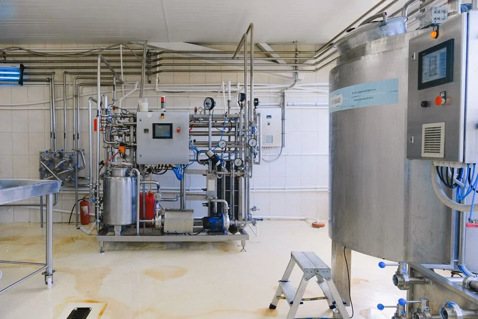
A serious pharmaceutical MBR supplier should answer these in writing before a purchase order is signed. Each one maps to a failure mode the design walkthrough above has already identified.
- Demonstrated pharmaceutical or hospital/pharma reference list with at least 12 months of operating data — not pilot data, full-load data.
- Flux and SAD curves at the project's actual MLSS and temperature, not a generic brochure curve.
- CIP recipe and projected membrane life in writing, with the foulant basis for the recipe stated.
- Cassette-level isolation and replacement procedure, including the lifting gear or floor-level access story.
- Compliance with PD CEN/TR 15897 as a baseline plus a documented deviation list for pharmaceutical-specific design choices (BSI, PD CEN/TR 15897).
On the sizing envelope, proposals should sit in the 10–2,000 m³/day integrated MBR range with flat-sheet modules in the 80–225 m² bracket producing 32–135 m³/day per module (DF-series working geometry). Ask for an energy model, not a single kWh/m³ number, and require the supplier to show how the model behaves at the project's minimum and maximum influent temperatures and COD. For any new API or antibiotic product, commission a pilot or a containerized MBR trial before committing to a full-scale order — the research does not quantify pilot cost, so this is a qualitative recommendation, not a price claim, but it is the cheapest insurance against a fouling profile the lab data did not capture.
Frequently Asked Questions
Is submerged MBR the right choice for high-COD pharmaceutical effluent?
Submerged is the default for medium and large pharmaceutical flows because the design envelope runs from 12,000 mg/L to 20,000 mg/L MLSS and the modern operating window is 10–20 days SRT at 10–15 g/L, which is the range where recalcitrant APIs, antibiotics, and solvents are partially attenuated (Wikipedia, Membrane Bioreactor). Side-stream MBR is reserved for niche cases, generally smaller-scale higher-strength applications where floor-level access for membrane replacement is a deciding factor.
What pore size and membrane material should I specify?
Default to 0.1 μm PVDF (DF-series flat-sheet geometry as a working value). PVDF is the most prevalent polymeric membrane material because of its long lifetime, chemical resistance, and mechanical resistance, and it covers the majority of pharmaceutical influents (Wikipedia, Membrane Bioreactor). Specify ceramic — alumina, SiC, titania, or zirconia — only when the CIP chemistry or solvent profile is harsh enough to shorten PVDF life unacceptably; the membrane supplier should justify the material choice with a documented chemical compatibility table for the actual CIP recipe.
How much does a pharmaceutical MBR cost to run?
Defend the OPEX in four buckets: aeration energy (the largest single line, driven by SAD and MLSS), pumping and recirculation, CIP plus pH-correction chemicals, and membrane replacement as a function of CIP discipline. The only energy benchmark the research supports is the modern low-energy side-stream figure of ~0.3 kWh/m³ of product, which is a useful order-of-magnitude reference but not a pharmaceutical-specific number. Request an energy model from each bidder based on the actual influent, and request a written CIP chemical budget and projected membrane life rather than a single $/m³ figure.
Can submerged MBR effluent be reused in the plant?
Submerged MBR effluent is typically below detection for TSS and most bacteria and is suitable for discharge or for RO/UF polishing to reuse quality (Wikipedia, Membrane Bioreactor). For boiler feed, cooling-tower makeup, or cleaning water, add a downstream industrial RO polishing system; the MBR's job is to remove the bulk COD, biomass, and colloidal load so the polishing membranes do not foul prematurely. Polishing is mandatory whenever boiler-feed quality is required.
How do I evaluate MBR suppliers?
Apply the evaluation checklist in the previous section: at least 12 months of pharmaceutical reference data, flux and SAD curves at the project's actual MLSS and temperature, written CIP recipe and projected membrane life, cassette-level isolation and replacement procedure, and PD CEN/TR 15897 compliance with a documented deviation list. Reject any quote that offers a single kWh/m³ number without an underlying energy model — influent variability will swing the real figure by a factor of two or more, and the only honest answer is a model, not a number.