
What an Anoxic/Aerobic + MBR Train Does
An anoxic/aerobic + MBR train is a three-zone activated-sludge process in which biological degradation and solid–liquid separation are folded into a single tank line. The influent first enters an anoxic zone where dissolved oxygen is held below 0.2 mg/L and heterotrophic bacteria reduce nitrate (NO₃-N) to nitrogen gas (N₂), consuming the carbon already present in the sewage. The mixed liquor then flows into an aerobic zone operated at DO 1.5–2.5 mg/L, where autotrophic nitrifiers oxidise ammonia to nitrate and heterotrophs oxidise BOD. From the aerobic zone, the sludge is recycled internally back to the anoxic zone — typically at 200–400% of the influent flow rate — to give nitrate a second pass through the anoxic reactor and drive total-nitrogen removal. The third zone is the membrane tank itself: a submerged PVDF flat-sheet or hollow-fibre cassette operating at MLSS 8,000–12,000 mg/L that physically retains solids on a 0.1 µm membrane rather than letting them settle in a clarifier.
For typical municipal sewage — COD 250–500 mg/L, BOD 150–300 mg/L, NH₃-N 20–45 mg/L, TN 30–60 mg/L, SS 150–300 mg/L — this train produces an effluent of COD <30–50 mg/L, BOD <5 mg/L, NH₃-N <1–5 mg/L, and SS near zero (per the 2021 ScienceDirect MBR review and the 2026 BF-OMBR performance study, which reported stable operation for 90 days at low temperature). The Qingdao Liuting Airport A/O-MBR plant, with a design capacity of 2,700 m³/d (1,000 m³/d in its first phase), was put into service in September 2003 as a reuse scheme for the terminal and ancillary facilities and remains the largest A/O-MBR installation of its kind in Asia (per the 2010 IEEE tech-economic analysis).
Step 1 — Build the Design Basis
Before any tank volume is drawn on a P&ID, lock seven inputs in a design basis memo. Without them, every downstream number is just a guess with units. The seven inputs are:
- Average daily flow Q (m³/d) and the peak factor (typically 1.5–2.0 for sewage; check local sewer design standards).
- Influent concentrations: COD, BOD, NH₃-N, TN, SS, and pH/temperature window.
- Effluent targets: for example China GB 18918-2002 Grade 1A, EU UWWTD 91/271/EEC for <10,000 PE plants, or a reuse specification (irrigation, toilet flushing).
- Mixed-liquor temperature (10–25 °C drives the nitrification rate constant and therefore SRT).
- Footprint constraint — MBR's main economic case is roughly 60% footprint reduction versus CAS, but only if the site can host the cassette skid height.
- Reuse intent — discharge vs irrigation vs toilet flushing sets the post-MBR barrier (UV, chlorine dioxide) and the need to meet EU Drinking Water Directive 98/83/EC parameters where applicable.
- Sludge handling destination — belt press, centrifuge, or drying bed determines the target SRT/MLSS combination.
Convert concentrations to loads: BOD load (kg/d) = Q (m³/d) × BOD (mg/L) ÷ 1,000. For Q = 500 m³/d and BOD = 200 mg/L, BOD load = 100 kg/d. This is the single number that drives the aerobic volume in Step 3 and the membrane area in Step 4.
| Design basis input | Typical municipal range | Source / standard |
|---|---|---|
| Average daily flow Q (m³/d) | 50–2,000 (this article's scope) | Project definition |
| Peak factor | 1.5–2.0 | Local sewer design code |
| Influent BOD (mg/L) | 150–300 | Typical municipal sewage envelope |
| Influent NH₃-N (mg/L) | 20–45 | Typical municipal sewage envelope |
| Influent TN (mg/L) | 30–60 | Typical municipal sewage envelope |
| Influent SS (mg/L) | 150–300 | Typical municipal sewage envelope |
| Effluent COD (mg/L) | <30–50 (GB 18918-2002 1A: ≤50) | China GB 18918-2002 |
| Effluent NH₃-N (mg/L) | <1–5 (1A: ≤5 at low temp; ≤8 in winter) | China GB 18918-2002 |
| Mixed-liquor temperature (°C) | 10–25 | Site climate |
Step 2 — Size the Anoxic Zone
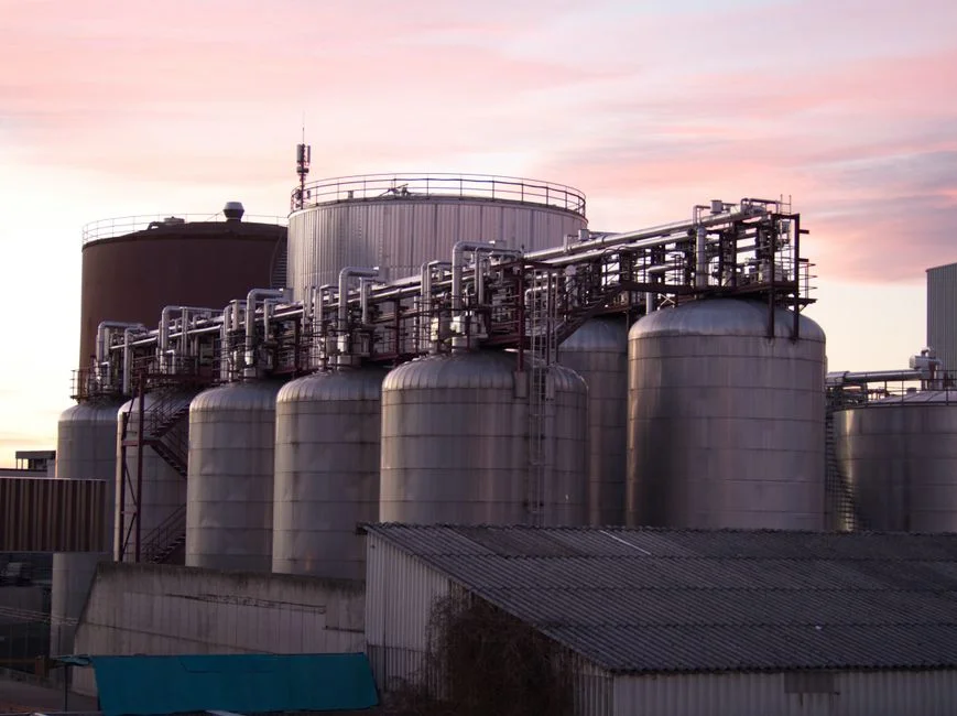
The anoxic volume is set by hydraulic residence time because denitrification is fast relative to nitrification and the limiting reagent is normally carbon, not volume. Use an anoxic HRT of 1–2 hours; 2 h is the conservative pick for low-C/N municipal sewage at 10–20 °C, 1 h is acceptable for higher-C/N industrial wastewater or warm-climate plants.
Anoxic volume equation: V_anoxic (m³) = Q (m³/d) × HRT (h) ÷ 24. For Q = 500 m³/d at HRT = 2 h, V_anoxic = 500 × 2 / 24 ≈ 42 m³.
After the volume is set, run a denitrification carbon check. Required nitrate to remove (kg NO₃-N/d) ≈ Q × (TN_in − TN_out) ÷ 1,000. Carbon available (kg COD-equivalent/d) ≈ Q × (COD_in − COD_effluent) ÷ 1,000. The widely used stoichiometric ratio is 2.8–3.0 kg COD consumed per kg NO₃-N reduced; if (COD_in − COD_effluent)/2.8 is less than the required nitrate removal, dose external carbon — methanol at ~2.5 kg CH₃OH per kg NO₃-N removed, or acetate at ~3.5 kg COD per kg NO₃-N. The internal recycle ratio R (200–400% of Q) is then the second lever: raising R increases the nitrate load returned to the anoxic zone and tightens TN, at the cost of pumping and aeration-tank short-circuiting.
Step 3 — Size the Aerobic + MBR Zone
The aerobic tank — often merged with the membrane tank as a single MBR basin — is sized by two independent checks. Run both and pick the larger volume.
Check A — F/M basis: target F/M = 0.05–0.15 kg BOD/kg MLSS·d. Lower end (0.05–0.08) suits high-MLSS MBR operation; upper end (0.10–0.15) suits low-loaded or low-temperature sites. V_aerobic = BOD load (kg/d) ÷ [F/M × MLSS (kg/m³)]. For BOD load = 100 kg/d, F/M = 0.10, MLSS = 10,000 mg/L = 10 kg/m³: V = 100 / (0.1 × 10) = 100 m³.
Check B — HRT basis: target aerobic HRT = 4–8 h. V = Q × HRT/24. For 500 m³/d at 6 h, V = 125 m³. Take the larger of A and B (125 m³ here) as the aerobic working volume.
Hold SRT at 15–30 days; this is the control knob for nitrification (≥10 d at 10 °C, ≥5 d at 20 °C) and for stable foam control. Calculate waste sludge flow: Q_w = V × MLSS ÷ (SRT × X_rss), with X_rss ≈ 0.8 × MLSS in the MBR tank. For V = 125 m³, MLSS = 10 kg/m³, SRT = 20 d, X_rss = 8 kg/m³: Q_w = 125 × 10 / (20 × 8) ≈ 7.8 m³/d.
Aeration intensity for membrane scouring is set independently of process oxygen demand. For 0.1 µm PVDF flat-sheet modules, supply 0.3–0.6 m³ air per m² membrane area per hour through coarse-bubble diffusers mounted directly beneath the cassette rack. This scouring air typically represents 30–50% of the total air demand at design flux and is the single biggest electrical load on the plant.
Step 4 — Calculate the Membrane Area
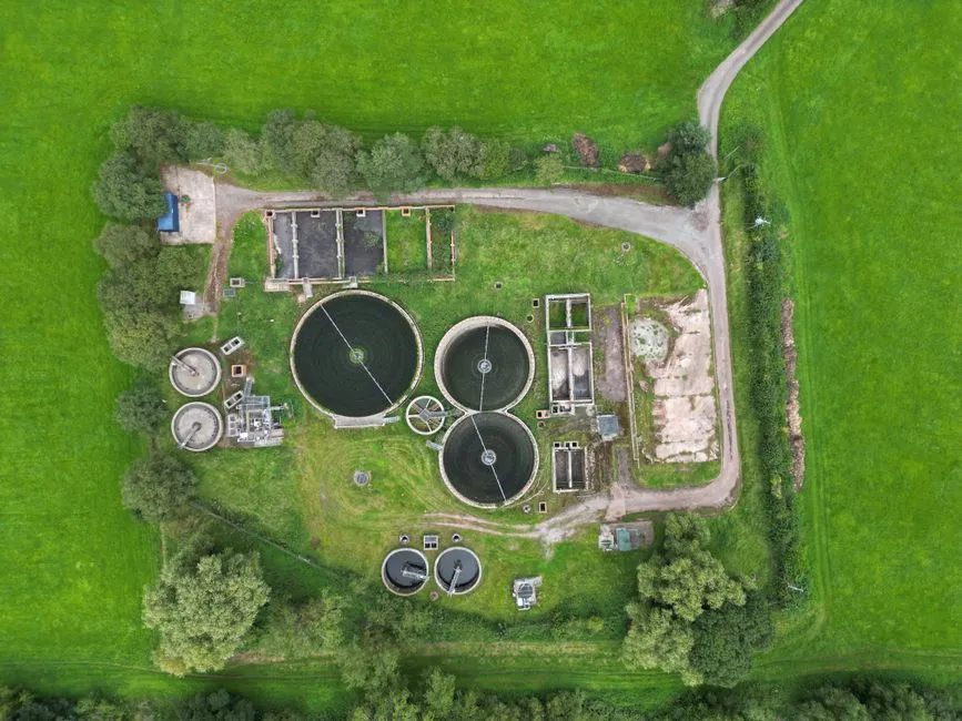
Turn the hydraulic design into a purchaseable number of cassettes. Design flux J for 0.1 µm submerged PVDF flat-sheet modules at 10–25 °C is 15–25 L/m²·h; pick 15 for conservative continuous duty on mixed sewage, 20 for typical municipal, 25 only on screened, low-oil influent. Net flux after backwash and relaxation losses is roughly 80–85% of the gross figure — use net flux for hydraulic balance, gross flux for the area equation.
Membrane area equation: A (m²) = Q (m³/d) × 1,000 ÷ [J (L/m²·h) × 24]. For Q = 500 m³/d and J = 20 L/m²·h: A = 500,000 ÷ 480 ≈ 1,042 m².
Round up to available module geometry. With 150 m² cassettes, you need 7 modules (1,050 m²) at minimum. Adding 15–25% redundancy for peak flow and one-cassette-out maintenance brings installed area to ~1,200 m², i.e. 8 × 150 m² modules. The DF-series PVDF flat-sheet membrane module ships in 80–225 m² per cassette and produces 32–135 m³/d per module at the 15–25 L/m²·h flux window, so a 500 m³/d plant lands cleanly on 6–8 cassettes. For peak flow, either oversize area by 20–30% or programme a peak-flux override up to 30–35 L/m²·h for short-duration peaks only; sustained operation above 30 L/m²·h on flat-sheet modules accelerates fouling and shortens chemical-cleaning intervals (a finding reinforced by the 2026 BF-OMBR low-temperature pilot, which kept flux steady over 90 days only because of conservative flux choice and intermittent aeration).
Design Parameter Reference Table
| Parameter | Typical 2026 range | Recommended default (municipal sewage) |
|---|---|---|
| Anoxic HRT (h) | 1–2 | 2.0 |
| Aerobic HRT (h) | 4–8 | 6.0 |
| MLSS (mg/L) | 8,000–12,000 | 10,000 |
| SRT (d) | 15–30 | 20 |
| F/M (kg BOD/kg MLSS·d) | 0.05–0.15 | 0.10 |
| DO setpoint, aerobic (mg/L) | 1.5–2.5 | 2.0 |
| Internal recycle ratio R (×Q) | 2–4 | 3 |
| Design flux, 0.1 µm PVDF flat-sheet (L/m²·h) | 15–25 | 20 |
| Scour aeration intensity (m³ air/m²·h) | 0.3–0.6 | 0.45 |
| Target effluent COD (mg/L) | <30–50 | <50 |
| Target effluent NH₃-N (mg/L) | <1–5 | <5 |
| Default membrane geometry (10–2,000 m³/d) | 0.1 µm PVDF flat-sheet | 0.1 µm PVDF flat-sheet |
| Default membrane geometry (>2,000 m³/d) | Hollow-fibre UF | Hollow-fibre UF |
Flat-sheet PVDF wins on the 10–2,000 m³/d band because cassettes can be pulled individually for cleaning without draining the tank. Above 2,000 m³/d, hollow-fibre UF modules give a higher packing density (m² per m³ of tank) and are typically the lower installed-cost option, although they tolerate less backpressure and need more careful air-scour design (per the 2021 ScienceDirect MBR review).
Worked Example: 50 m³/d Hotel Sewage
Inputs: Q = 50 m³/d, BOD = 250 mg/L, NH₃-N = 30 mg/L, reuse target = irrigation. BOD load = 12.5 kg/d. Step 2: anoxic volume = 50 × 2 / 24 = 4.2 m³ → round to 5 m³. Step 3: aerobic volume on F/M basis = 12.5 / (0.1 × 10) = 12.5 m³; aerobic volume on HRT basis = 50 × 6 / 24 = 12.5 m³. Both checks converge at 13 m³ MBR tank. Step 4: membrane area = 50,000 / (20 × 24) ≈ 104 m² → specify one 150 m² DF flat-sheet cassette (the DF-series PVDF flat-sheet membrane module) for ~30% redundancy, or two 80 m² modules with tighter footprint. A skid-mounting integrated MBR system sized to 50 m³/d will land inside a single 6 m freight container, making it a sensible package for a remote resort or factory gatehouse — sizing logic identical to a 500 m³/d plant, just rescaled.
Worked Example: 500 m³/d Municipal Train
Inputs: Q = 500 m³/d, BOD = 200 mg/L, NH₃-N = 30 mg/L, target = China GB 18918-2002 Grade 1A discharge. BOD load = 100 kg/d. Step 2: V_anoxic = 500 × 2 / 24 ≈ 42 m³. Step 3: V_aerobic from F/M = 100 / (0.1 × 10) = 100 m³; V_aerobic from HRT = 500 × 6 / 24 = 125 m³ → take 125 m³. The aerobic and MBR zones are merged in a single basin at MLSS 10,000 mg/L with a partition baffle. Step 4: A = 500,000 / 480 ≈ 1,042 m² → 8 × 150 m² DF-series flat-sheet cassettes, 1,200 m² installed, ~15% redundancy. Total plant footprint reduction is on the order of 60% versus a conventional activated-sludge train with a secondary clarifier (per the 2021 ScienceDirect MBR review), which is typically the economic trigger for picking MBR at this scale. For a head-to-head cost, energy and compliance view, see our MBR vs activated sludge comparison.
Operational Checks After Commissioning
Calculations are only credible if the plant reaches the assumed numbers in the first 30–90 days. Four field checks close the loop:
- MLSS window: confirm MLSS sits in 8,000–12,000 mg/L within 2–3 SRTs of start-up. A rapid drop indicates sludge washout (check WAS pumps and effluent TSS); a slow rise indicates inadequate wasting or foaming/scum trapping.
- Trans-membrane pressure (TMP) and permeability: clean-water permeability should hold within ±15% for 60–90 days before the first chemical cleaning — a benchmark the 2026 BF-OMBR pilot met during 90 days of stable low-temperature operation. Trigger a clean-in-place (CIP) when permeability drops 20–25% below baseline or TMP rises above the manufacturer-set ceiling (typically −30 to −50 kPa for suction-side operation).
- Denitrification confirmation: measure NO₃-N at the anoxic outlet and the final effluent. If TN is high and the anoxic outlet NO₃-N is high, increase internal recycle R within the 200–400% window; if anoxic outlet NO₃-N is already low and TN is still high, the bottleneck is nitrification and the cure is longer SRT, not more recycle.
- Relaxation/backwash cycle: programme 9 min filtration / 1 min relaxation as the baseline, with a periodic backpulse using permeate or chlorinated side-stream. This combination is the consistent recommendation in the intermittent-aeration fouling-mitigation literature on dairy MBRs and translates cleanly to municipal duty.
Track all four numbers weekly for the first quarter. Once the plant holds the design window for two consecutive months, the calculated sizing is operationally verified — and the only remaining question is membrane replacement budgeting, typically 5–8 years for PVDF flat-sheet depending on influent oil/grease control.
Frequently Asked Questions
What is the anoxic HRT for an A/O + MBR plant?
1–2 hours; use 2 h for municipal sewage at 10–20 °C, and 1 h for higher-C/N industrial wastewater or warm-climate sites where denitrification kinetics are faster.
What MLSS should an MBR run at?
8,000–12,000 mg/L is the standard operating window for submerged PVDF MBRs. Above ~14,000 mg/L the mixed-liquor viscosity rises, oxygen-transfer efficiency drops, and membrane fouling accelerates sharply — so push MLSS up only if your diffuser system and scour aeration can carry the load.
How is MBR membrane area calculated?
Membrane area A (m²) = Q (m³/d) × 1,000 ÷ [design flux (L/m²·h) × 24]. For 0.1 µm submerged PVDF flat-sheet modules at 10–25 °C, design flux is 15–25 L/m²·h. Always add 15–25% area margin for peak flow and one-cassette-out maintenance.
How much smaller is an MBR plant than conventional activated sludge?
Around 60% smaller footprint, because the secondary clarifier and most of the tertiary stage are removed. The MBR basin replaces the aeration tank, clarifier and sand/UF filter in a single step, with the trade-off being higher electrical load (mainly membrane scour air) and a membrane-replacement line item every 5–8 years.
When should I pick A/O + MBR over A²O + MBR?
A/O + MBR is enough when the discharge or reuse target requires carbon and ammonia removal but not biological phosphorus removal. A²O + MBR (anoxic / anaerobic / aerobic + MBR) is needed when simultaneous biological P removal is required to hit a TP ≤0.5 mg/L target — adding an anaerobic zone ahead of the anoxic basin and accepting the higher internal-recycle complexity that goes with it. For a packaged small-plant perspective, the packaged MBR STP buyer's guide walks through the same A/O vs A²O decision at hotel scale.