

The 2026 Compliance Reality for Petroleum Plants Near Commerce City
A Notice of Violation dated January 2026 lands on a terminal manager's desk in Adams County, citing a hexane-extractable material (HEM) reading 1.6× the daily-maximum ceiling, flagging a 30-day cure window, and carrying a footnote that the next two missed reports will escalate the event to Significant Noncompliance (SNC) under 40 CFR Part 403. That letter is the reality of the 2024–2026 National Pretreatment Program review cycle, which has pushed receiving POTWs to re-tighten Technically Based Local Limits (TBLL) as headworks capacity tightens and South Platte watershed reuse demand rises. The receiving POTW for most Commerce City and Adams County terminals is the Metro Wastewater Reclamation District (MWRD), whose TBLL review typically runs on a five-year cycle aligned with NPDES permit renewals and biosolids capacity re-evaluations; the 2024–2026 cycle was driven by a combination of stricter Colorado water-quality standards for the South Platte and headworks-loading concerns flagged during the prior cycle's audit.
Typical 2026 permit ceilings at MWRD for petroleum-category Significant Industrial Users (SIUs) sit in the 100–200 mg/L HEM daily-max range, approximately 250 mg/L TSS, with benzene, toluene, ethylbenzene, xylene (BTEX) and total petroleum hydrocarbons (TPH) sized to the local Maximum Allowable Industrial Loading (MAIL) allocation. The SNC triggers are federal and unforgiving: any single-day exceedance of a numerical limit by ≥1.5×, or any limit exceeded on more than 5% of measurement days in a six-month window, or any required report more than 30 days past due (per EPA National Pretreatment Program, 40 CFR Part 403). The consequence chain runs linearly: Notice of Violation → SNC finding → Show Cause hearing → administrative order, surcharges, mandated zero-discharge status, or permit termination. For a 2026 terminal, the cost is operational, not theoretical — and the engineering decisions made this quarter determine which branch of that chain the plant travels.
Regulatory Chain: CWA, 40 CFR Part 403, MAHL, and the MWRD Permit
The citation chain a Commerce City engineer can hand to a regulator runs Clean Water Act §307(b) (33 U.S.C. § 1251 et seq.) → EPA General Pretreatment Regulations at 40 CFR Part 403 → EPA's Local Limits Development Guidance (Chapter 2, MAHL Decision Tree) → MWRD-adopted Technically Based Local Limits (TBLL) → individual Industrial User permit. The MAHL decision tree walks five steps: Step 1 identifies pollutants of concern (POCs), Step 2 collects headworks data, Step 3 calculates Maximum Allowable Headworks Loadings (MAHLs) for each POC, Step 4 designates and implements local limits, and Step 5 addresses collection-system concerns such as corrosion, flammability, and worker safety (per EPA Local Limits Development Guidance, 2004/2021 update). Four inputs drive every MAHL: NPDES effluent limits on the receiving POTW, Colorado water-quality standards for the South Platte, Part 503 biosolids numerical criteria, and NIOSH/ecology protection factors (per the 2020 St. Joseph, MO TBLL evaluation by Black & Veatch).
The Industrial User (IU) trigger is the first gate: a facility that discharges process wastewater to a POTW, or that contributes ≥25,000 gpd of non-domestic waste, qualifies. Most petroleum bulk plants are noncategorical SIUs; dedicated refinery and fuel-blending operations may be categorical under 40 CFR Part 419 (per St. Joseph, 2020 TBLL). The distinction matters for permit stringency but not for the daily reporting burden. What does matter is the difference between MAHL and MAIL: MAHL is the headworks ceiling the POTW can absorb without violating any of its downstream permits; MAIL is the per-IU allocation the POTW prints on a permit, derived by dividing MAHL by all contributing industrial flow plus uncontrolled domestic load. For a 2026 MWRD permit, the daily-max HEM number on the page is MAIL, not MAHL — and the engineer should know which ceiling the MWRD used to back-calculate it. Colorado Discharge Permit System (CDPS) pretreatment coordination overlays federal 40 CFR Part 403 with state authority, which is why MWRD's TBLL adoption goes through both EPA Region 8 review and CDPHE sign-off.
The HEM, BTEX, and TPH Parameters That Drive Permit Design
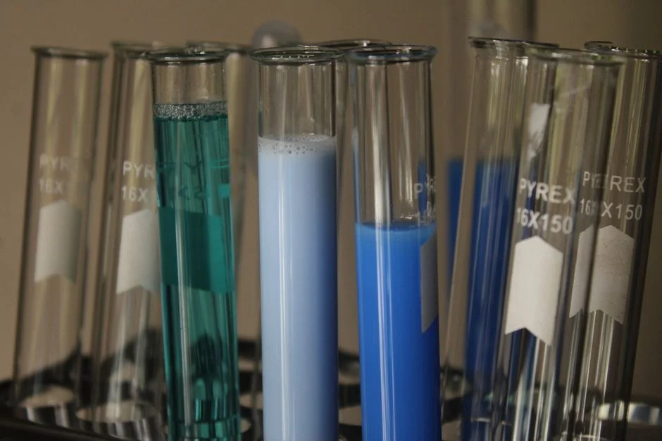
Hexane Extractable Material (HEM) is the federally used surrogate for fats, oils, and grease in U.S. pretreatment, defined in 40 CFR § 401.16 and measured by EPA Method 1664A using n-hexane extraction. It is the parameter most MWRD permits cite as "O&G," and it is the number that lands in the Notice of Violation. Typical 2026 permit ceilings run 100–200 mg/L HEM daily-maximum and approximately 250 mg/L TSS (per the 2020 St. Joseph, MO TBLL). Stricter POTWs in water-reuse basins push daily-max HEM toward 50 mg/L — a trend that matters along the South Platte, where reuse demand is intensifying (per the ACS ES&T Engineering 2021 review on U.S. industrial water scarcity and reuse).
BTEX and TPH are the lead parameters for permit negotiation, not HEM. The MAHL allocation that MWRD calculates for benzene and TPH often constrains daily flow more than O&G does, because benzene carries the lowest headworks-loading ceiling of the four BTEX components and TPH is mass-loaded against the South Platte water-quality criteria. Engineers should request the MWRD's MAHL calculation worksheet for each parameter before signing the permit — the worksheet will show whether the limit was set by effluent-quality, biosolids, or air-quality concerns, and which ceiling the operator can negotiate. Watchlist parameters for 2026–2028 include individual BTEX fractions with daily-max and monthly-average limits, TPH fractions split by carbon range (C6–C12 gasoline range, C12–C28 diesel range, C28+ oil range), and ammonia where biological polishing is in service.
The Four-Stage Pretreatment Train — and Why the Order Is Non-Negotiable
A petroleum terminal pretreatment train has four stages, and the sequence is dictated by droplet-size distribution logic, not vendor preference. Stage 1 is source segregation: keeping hydrocarbon-contaminated streams out of clean stormwater shrinks the volume hitting the treatment train by 40–70% in field retrofits and converts most of the remaining flow from "design problem" to "design choice" (HydropureWater field data, 2026). The hardware is segregated laterals on product-handling pads, covered and locked dump valves on coalescers, drip pans under loading arms, and dedicated oil/water sewering on truck loading islands.
Stage 2 is primary oil/water separation — either an API gravity separator sized for ≥30 minutes residence at peak flow, or a Corrugated Plate Interceptor (CPI) with 1–2 in plate spacing and corrugation near 45°. This stage handles free oil at ≥60–150 µm droplet size, the band that accounts for most of the mass loading from tank-bottom water and coalescer dumps. Stage 3 is emulsified-oil polishing with a Dissolved Air Flotation (DAF) system, where micro-bubbles generated at 60–90 psig saturation pressure float oil droplets down to 10–25 µm. Surface hydraulic loading in oilfield service runs 2–5 gpm/ft², and air-to-solids ratio (ASR) carries a 20–30% safety margin to absorb slug loads. Stage 4 is biological or adsorption polishing — Moving Bed Biofilm Reactor (MBBR) or activated sludge for ammonia and sulfide, granular activated carbon where the train has to swing to <20 mg/L for a water-reuse loop.
Why a single-technology approach fails: tank-bottom water and coalescer dumps carry free oil at ≥150 µm, which blankets DAF micro-bubbles and crashes ASR; wash-rack water is emulsified by surfactants with droplet sizes below 50 µm, which a CPI alone cannot break. The robust path is CPI or API primary, then DAF polish, sized with margin on hydraulic and ASR. A Dissolved Air Flotation (DAF) system is the reference unit for the Stage 3 polish on Commerce City tank-bottom and wash-rack streams.
Choosing the Primary Separator: API, CPI, Coalescer, and DAF Compared
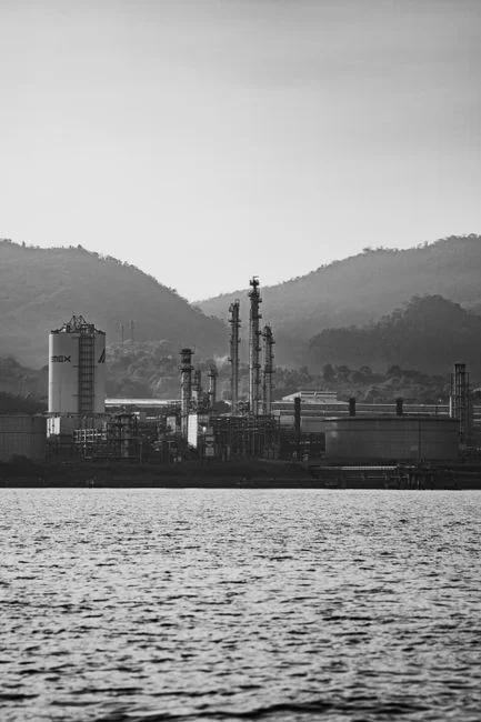
The four primary technologies sit in different performance bands and are not interchangeable. The table below maps droplet size, surface loading, best-fit scenario, and the key limitation for each:
| Technology | Target droplet size | Surface loading / spec | Best-fit scenario | Key limitation |
|---|---|---|---|---|
| API gravity separator | ≥150 µm (free oil) | ≥30 min residence at peak flow | High-throughput marine/terminal, large flow swings | Cannot break emulsions; large footprint |
| CPI (corrugated plate interceptor) | 60–150 µm (free oil) | 1–2 in plate spacing, ~45° corrugation | Small-to-mid terminal with steady flow; retrofit into existing concrete vault | Rarely meets <100 mg/L HEM on emulsified waste; plate fouling risk |
| Coalescer (plate or multimedia) | 10–25 µm (emulsified/colloidal) | 5–10 gpm/ft² (vendor-specific) | Polishing stage or low-flow sites with strict <50 mg/L needs | Higher O&M; media replacement 1–3 yr |
| DAF as primary | 10–25 µm (emulsified) | 2–5 gpm/ft² surface; ASR 20–30% margin | Truck-loading rack with emulsified oils; as primary only where free oil is pre-strained | Slug-sensitive without upstream primary; needs air saturation system |
Field guidance: a DAF alone without a primary gravity stage fails under slug loads from coalescer dumps, because free oil blankets the bubble surface and crashes ASR. A CPI alone rarely meets a 100 mg/L HEM limit on emulsified wash-rack water — it removes free oil efficiently but does not address sub-60 µm droplets (HydropureWater field data, 2026). The robust path for a U.S. petroleum bulk plant is CPI or API as primary, then DAF as the emulsified-oil polisher, sized with a 20–30% safety margin on hydraulic and air-to-solids loading. Engineers weighing DAF against conventional clarification in a different service can review the DAF vs clarifier decision guide for additional context on the technology trade.
Commerce City–Specific Design Wrinkles: Altitude, Freeze, and Watershed Reuse
Two local factors derate any DAF or outdoor separator design along the South Platte corridor, and neither appears in a generic U.S. explainer. The first is altitude: Commerce City sits at approximately 5,280 ft elevation, where atmospheric pressure is roughly 83% of sea-level standard. Henry's Law governs DAF air saturation, and lower partial pressure means less dissolved air per unit of saturator volume at the same pressure and temperature. The field consequence is that a DAF sized at sea level will deliver proportionally less air-to-solids ratio at altitude, eroding the 20–30% ASR safety margin. The mitigation is to oversize the saturation tank, raise saturation pressure within pump and vessel ratings, or add a booster compressor on the recycle line to preserve the design ASR envelope.
The second factor is freeze protection. Outdoor API and CPI units along the South Platte need to be designed for design ambient around -20°F, with buried or insulated vaults, heat-traced dump valves, and enclosed skimmer housings. A frozen dump valve fails closed during a cold snap, then releases as a slug load on the first thaw — that slug hits the DAF with free oil at ≥150 µm and crashes ASR in a single event. The standard mitigation is heat trace on all dump-valve bodies, insulation on exposed oil/water piping, and a sample-port design that does not freeze closed at -20°F. The physics and the failure mode are the same as for any outdoor wastewater train in a continental-interior climate, but the design air temperature is colder than most U.S. explainers assume (HydropureWater field data, 2026).
A third local factor is watershed reuse. The South Platte basin is on the industrial water-scarcity watchlist, and stricter 50 mg/L HEM ceilings are plausible by 2027–2028 (per the ACS ES&T Engineering 2021 review on U.S. industrial water scarcity and reuse). Stormwater segregation also matters more in Colorado than in coastal climates: spring snowmelt combined with summer convective storms can produce 3–5× design hydraulic peaks in a single event, and the slug load on a primary separator during peak flow is the most common cause of HEM carryover in field retrofits. A staged equalization basin ahead of the train is the standard mitigation.
Three Numbers That Drive a Defensible Design
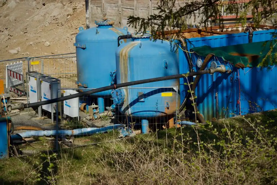
Three numbers — plus one Commerce City–specific fourth — must be locked in before talking to a vendor. First, peak instantaneous flow in gpm or m³/h, not the daily average. A coalescer dump or tank drop can spike 3–5× the daily mean, and the primary separator must hold its Reynolds-number cap and Froude-number floor at that peak (HydropureWater field data, 2026). Second, daily O&G load in lb/day or kg/day, calculated from tank turnover, wash-rack volume, and loading-arm drip rates. Third, target residual O&G in mg/L, taken from the MWRD permit ceiling and ideally set 20–30% below it as a safety margin so a single upset does not push the terminal into NOV territory.
The fourth number, specific to Commerce City and the South Platte corridor, is design air temperature, used to size heat tracing, vault insulation, and enclosure heating on outdoor API/CPI/DAF equipment. Standard ASHRAE design data for the Denver Metro area places the 99% heating design temperature near -10°F, but operators along the South Platte routinely spec to -20°F to absorb inversions and cold-pool events. The cost difference between -10°F and -20°F design ambient is small in heat-trace loading, but the operational difference during a polar vortex is the difference between a train that runs and a train that slug-loads the DAF on the first thaw. For chemical conditioning ahead of the DAF, an automatic chemical dosing system sized to the design peak flow keeps coagulant and flocculant ratios stable through the slug.
2026 Self-Monitoring Cadence and the SNC-Avoidance Playbook
The minimum self-monitoring cadence most POTWs expect from a 2026 petroleum bulk plant is: daily visual free-oil inspection at the outlet weir (paper or digital log, dated and initialed), weekly TSS grab, monthly HEM composite (EPA Method 1664A, 24-hour flow-proportional where the permit specifies), and 24-hour flow-proportional BTEX/TPH composite where the local limit is non-zero. Sampling taps must be accessible, the flow meter calibrated annually, and the chain-of-custody defensible — most SNC findings originate from sampling-procedure deficiencies, not from underlying treatment performance.
| Parameter | Frequency | Method | Documentation | Trigger if missed |
|---|---|---|---|---|
| Free oil (visual) | Daily | Outlet weir inspection | Log sheet, dated and initialed | BMP gap, audit finding |
| TSS | Weekly | Grab | Lab certificate, chain-of-custody | >30 days late = SNC risk |
| HEM (O&G) | Monthly | EPA Method 1664A, 24-hr flow-proportional composite | Lab certificate, flow record, chain-of-custody | Exceedance = NOV; 2 in 12 mo = SNC |
| BTEX / TPH | Monthly (where limit is non-zero) | 24-hr flow-proportional composite | Lab certificate, chain-of-custody | Exceedance = NOV; ≥1.5× = direct SNC |
| Best Management Practice | Cadence | Documentation | Owner | Audit value |
| Spill containment around ASTs | Continuous / weekly visual | Inspection log + photo | Operations | Eliminates ~25% of common audit findings |
| Covered/locked dump valves | Continuous / monthly check | Lockout log | Operations | Eliminates slug-load excursions |
| Segregated sewer laterals on pads | Continuous / annual review | Sewer map revision | Engineering | 40–70% volume reduction at source |
| SPCC plan (40 CFR Part 112) tied to sewer map | Reviewed every 5 yr; certified by PE | Written plan, PE signature | EHS / Engineering | Eliminates ~50% of common audit findings |
The consequence matrix is linear and avoidable: one late monthly report triggers a Notice of Violation; two in twelve months escalate to SNC; SNC triggers a Show Cause hearing and potential permit action. A terminal that runs the BMP list above, files reports on the 15th of every month without exception, and keeps a pre-audit file using the EPA National Pretreatment Program audit checklist categories will not see an SNC finding in 2026 (HydropureWater field data, 2026). Sludge generated by the train is handled separately; the sludge handling and dewatering comparison covers the dewatering side of the mass balance for terminals that already operate a filter press or belt press downstream.
Fast-Track Recovery When a Notice of Violation Has Already Arrived
Once the NOV has landed, the playbook is documented and runs on a 30-day clock. Step 1: confirm sampling integrity by re-pulling a flow-proportional HEM composite within 7 days, with full chain-of-custody, to rule out a sampling-procedure SNC. Step 2: audit the train — check dump-valve seals, confirm DAF saturation pressure holds 60–90 psig under load, and verify ASR performance against the 20–30% margin. Step 3: if volume hit the train, retrofit source segregation on the truck loading island laterals, which recovers 40–70% capacity at the head of the train. Step 4: rent a temporary DAF or rebalance coagulant chemistry while the permanent fix is engineered, following the emergency DAF case study pattern used for failing FOG lagoons. Step 5: file the cure report on the 15th of the month without exception, documenting each step above with photos, lab certificates, and dated logs, to break the NOV-before-SNC chain. The 30-day cure window is the entire budget; the cure report is the only document that resets the clock.
Frequently Asked Questions
What are the 2026 MWRD permit ceilings for HEM, TSS, BTEX, and TPH at a Commerce City petroleum terminal?
Typical 2026 MWRD ceilings for petroleum-category SIUs run 100–200 mg/L HEM daily-maximum and approximately 250 mg/L TSS, with BTEX and TPH sized to the local MAIL allocation (per the 2020 St. Joseph, MO TBLL methodology). Stricter POTWs in water-reuse basins push daily-max HEM toward 50 mg/L, and the South Platte basin is on that watchlist.
What triggers Significant Noncompliance under 40 CFR Part 403 in 2026?
EPA's National Pretreatment Program triggers SNC on any of three conditions: a numerical limit exceeded by ≥1.5× for any single day, a numerical limit exceeded on more than 5% of measurement days in a six-month window, or a required report more than 30 days past due. An SNC finding can lead to administrative orders, surcharges, mandated zero-discharge status, or permit termination.
Why does a DAF alone fail to meet 100 mg/L HEM on a Commerce City wash-rack stream?
A DAF without an upstream primary separator fails because free oil from coalescer dumps and tank drops blankets the micro-bubbles and crashes the air-to-solids ratio. The robust configuration is a CPI or API primary stage ahead of the DAF, sized with a 20–30% ASR margin and 2–5 gpm/ft² surface hydraulic loading.
How does the 5,280 ft elevation at Commerce City derate a DAF design?
Atmospheric pressure at 5,280 ft is roughly 83% of sea-level standard, so Henry's Law delivers proportionally less dissolved air per saturator volume at the same pressure. The mitigation is to oversize the saturation tank, raise saturation pressure within equipment ratings, or add a booster compressor on the recycle line to preserve the 20–30% ASR safety margin.
What is the fastest path back into compliance after a Notice of Violation?
Re-pull a flow-proportional HEM composite within 7 days with full chain-of-custody, audit the train for dump-valve seal failure and DAF pressure loss, retrofit source segregation on truck loading laterals to recover 40–70% capacity, rent a temporary DAF or rebalance chemistry, and file the cure report on the 15th of the month to break the NOV-before-SNC chain.
Related Equipment
- Dissolved Air Flotation (DAF) system — specifications, capacity range, and technical data
- automatic chemical dosing system — specifications, capacity range, and technical data