What Actually Fails on an MVR Evaporator
Heater-tube scaling and vapor-compressor vibration are the two failure modes that account for the majority of unplanned MVR shutdowns in chemical, pulp-and-paper and ZLD service. The 2019 Gotsu Mill retrofit documented by JTAPPI (Japan Technical Association of the Pulp and Paper Industry) names both explicitly: scale plugged the heater tubes and vibration forced the compressor offline, and the mill only hit its 111% production uplift and 13% energy saving versus multiple-effect evaporation after both root causes were resolved at the source (S1).
The reason these two components dominate the failure list is the physics of the forced-circulation body. No boiling takes place inside the heat exchanger; the loop is held under enough pressure to suppress flashing, with tube-side velocity held at 2.0–3.5 m/s to keep solids swept off the wall (HydropureWater field data, 2026). The heat-transfer coefficient on the boiling side targets roughly 1,800 W/m²·K, and a centrifugal compressor lifts the secondary vapor by about 20°C to provide that ΔT (HydropureWater field data, 2026). When either side drifts — the heat exchanger fouls, or the compressor loses mechanical balance — evaporation rate collapses long before the unit trips on a hard interlock.
The ENCON process layout that ships most North American MVR skids makes the component map explicit: preheated feed → forced circulation → shell-and-tube heat exchanger → orifice plate → separation tank → vapor to compressor suction → compressed vapor back to the heating side (S2). Anyone maintaining that train needs to be able to point at each box on that line, which is what the next section is for. For the broader engineering context on high-salinity feeds, see the MVR evaporator engineering guide for high-salinity wastewater.
The MVR Loop in One Diagram-Worth of Words
Picture a single closed loop. Preheated feed enters a mixing tee where it joins a large circulating stream. That stream is pushed by a centrifugal circulation pump through a shell-and-tube heat exchanger, where compressed vapor condenses on the shell side and gives up its latent heat. The heated liquor then passes through an orifice plate that drops the pressure, the liquor flashes into a separation tank, and the vapor rises off the top while the concentrated liquor leaves the bottom. Vapor drawn off the top of the separator feeds the suction of the vapor compressor; the compressor raises it in pressure and saturation temperature, and the now-hot vapor returns to the shell side of the heat exchanger to repeat the cycle (S2).
Every component on that line is a maintenance-relevant item. The circulation pump, main heat exchanger, vapor compressor, separator, distillate sump, CIP skid and rupture disk each have a defined service interval (S2). The instrumentation layer is part of the loop as well: Rosemount-class temperature, pressure and level transmitters are the eyes of the operator, and when they drift they generate false maintenance symptoms that send people into the wrong component (S2).
The pressure-vessel body is built to ASME Section VIII, with a mechanical rupture disk on the vapor space as the last line of overpressure protection (S2). That disk is on an annual replacement schedule, not a run-to-failure schedule, and the relief-device test record is what an inspector will ask for first.
Daily and Weekly Operator Rounds
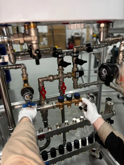
On every shift, log six numbers: compressor discharge temperature, separator pressure, ΔP across the heat exchanger, circulation flow, motor current on the compressor, and distillate conductivity (S2, S3). These six readings, trended against each other, are how you catch a problem on day one instead of day seven. A rising ΔP at constant circulation flow is the textbook signature of scaling; a falling compressor discharge temperature at constant load indicates either fouled tubes on the heating side or a degraded ΔT across the loop (S3).
Weekly, walk the compressor with a handheld vibration collector and compare to the baseline stored in the CMMS. The Gotsu Mill case is instructive here: vibration was traced to fouling on the rotor, and an open clean resolved it. No bearings were replaced, no coupling was re-aligned, no rotor was swapped (S1). The instinct to default to "replace the bearing" is the most expensive error a maintenance planner can make on a forced-circulation MVR.
On the same weekly round, inspect sight glasses and the rupture disk for any sign of leakage or distortion, verify the distillate-sump transfer pump cycles on level, and check pH and conductivity on the feed stream. On a modern ENCON-class skid with Allen-Bradley controls and automated CIP sequencing, the operator is verifying alarms and trend direction rather than chasing readings by hand (S2). The discipline is to read the trends, not to stare at the gauge.
Heat Exchanger Maintenance: Scale, CIP and Tube Cleaning
Scale is the dominant MVR failure mode, and the fouling signature is consistent: rising ΔP across the exchanger at constant flow, falling overall U-value, and rising compressor power for the same evaporation rate (S3, S4). If all three move together, the heater is fouling and a CIP is overdue.
CIP chemistry is site-specific and should be validated against the boil-point rise and TDS of the feed rather than copied from a manual. The general framework is straightforward: acid CIP (typically inhibited HCl or sulfamic-based) for calcium carbonate and silica scale; caustic plus a surfactant for organic and biofilm fouling; temperature held at the manufacturer's validated setpoint, usually within 10–15°C of the normal evaporation temperature to keep thermal stress on the gaskets or tube sheets bounded. Concentration ranges and contact time are tuned per site based on the chemistry of the scale, not assumed.
The frequency decision is the single most useful sentence in this article. With a tuned antiscalant program and a softening step ahead of the MVR, a well-run installation cleans every 90 days; with a mis-tuned or manual upstream dosing skid, the same heater stops every 10–14 days (HydropureWater field data, 2026). The MVR is not the unit that decides its own cleaning interval — the dosing skid in front of it does. The automatic chemical dosing skid ahead of the evaporator is the unit operation that sets the cleaning cadence.
Mechanical cleaning is a last resort for the shell-and-tube body. When chemistry fails, the path is: isolate and depressurize, open the channel head, hydroblast the tube bundle at controlled pressure to avoid tube damage, and inspect the tube sheets for chloride pitting if the brine is high-Cl⁻ (S3). At Gotsu Mill, the team added a vapor-drain flush to the operating routine so the heater stayed clear between full CIP cycles (S1). That is the kind of low-cost procedural fix that often outperforms a more aggressive chemical program.
For plate-and-frame exchangers, the cleaning procedure is shorter — open the frame, spray, rinse, close — but the gasket inspection interval is shorter too, because elastomers age faster than a tube bundle. The trade-off is real: a plate-and-frame gives better heat transfer in a smaller footprint, at the cost of more frequent mechanical attention; a shell-and-tube tolerates fouling longer but is heavier and harder to open when you finally have to (S2).
| Parameter | Action Threshold | Likely Cause | Response |
|---|---|---|---|
| ΔP across heat exchanger | Rises 15–20% from clean baseline at constant flow | Scale or biofilm on heating or process side | Schedule acid or caustic CIP within the shift |
| Compressor discharge temperature | Falls 3–5°C from baseline at constant load | Fouled tubes reducing ΔT, or surge | Check circulation flow and heat-exchanger ΔP before touching the compressor |
| Compressor motor current | Rises 5–10% at constant evaporation rate | Higher compression work from heavier vapor or fouled impeller | Compare against baseline; inspect compressor internals at next outage |
| Distillate conductivity | Exceeds site limit (often 50–100 µS/cm) | Carryover from separator, probe drift, or sump pump failure | Verify probe calibration; check demister and level control |
| Vibration velocity (compressor bearings) | Exceeds baseline by >25% or hits alarm setpoint | Fouling, imbalance, alignment drift | Open clean before replacing bearings (Gotsu Mill precedent, S1) |
Vapor Compressor Service: Rotary Lobe vs. Centrifugal
MVR vapor compressors come in two families, and they have very different maintenance profiles. Rotary lobe (roots) blowers are used on smaller units; centrifugal compressors are used on larger ones (S2). A rotary lobe compressor is a positive-displacement machine with two timing-gated rotors running on a fixed clearance — the service items are oil change, timing-gear inspection, shaft-seal leak check, and rotor-tip clearance measurement. A centrifugal compressor is a continuous-flow machine with an impeller in a volute; the service items are bearing temperature and vibration trend, impeller fouling, and surge-margin verification (S2).
The economic weight of the compressor is large enough that efficiency loss shows up on the electricity bill within a single shift. A 10 t/h water-evaporation MVR draws on the order of 250–350 kW on the compressor alone, against a steam equivalent of about 4–5 t/h of saturated 0.6 MPa steam for a multi-effect evaporator of the same capacity (HydropureWater field data, 2026). Anything that pushes compressor power up by 10% is a five-figure annual cost line on its own.
The maintenance ceiling is set by physics. A centrifugal compressor can lift secondary vapor by about 20°C across the heating surface; a centrifugal fan or blower — sometimes used on the smallest units — tops out near 9°C (HydropureWater field data, 2026). That is the operating window the rest of the train has to live inside, and it is also the reason the cleaning interval matters so much: a fouled heat exchanger with a falling U-value eats directly into a ΔT budget that the compressor cannot extend.
The Gotsu Mill lesson is worth restating: when vibration appears on the compressor, the first move is to open the compressor and inspect for fouling or build-up, not to book a bearing replacement (S1). Bearing swap is the most expensive, lowest-yield response to a vibration event on an MVR compressor.
Separator, Distillate Sump and Instrument Loop
The separator tank, distillate sump and instrument loop are the supporting equipment that gets neglected when the heat exchanger and compressor are eating the maintenance budget. They fail quietly, and they fail expensively.
On the separator, inspect the demister pad for fouling or collapse, check the automatic bottoms-discharge valve for sticking, and verify the level transmitter calibration against a manual dip (S2). A separator that carries liquid over into the compressor suction will waterhammer the rotor and trip the unit. On the distillate sump, confirm the transfer pump runs on demand and that the conductivity probe is calibrated — a stuck probe will allow contaminated distillate to recycle back to feed, where it will scale the very heat exchanger the operator is trying to protect (S2).
The instrument loop deserves its own paragraph because instrument drift is the silent cause of most "we scaled up overnight" events. Rosemount, Endress+Hauser and Ashcroft-class transmitters should be on a documented calibration schedule with traceability, not on a "calibrate when it looks wrong" basis (S2). The cost of a calibration contract is trivial against the cost of a single unscheduled CIP caused by a level transmitter that has drifted two percent low and let the separator run dry.
The rupture disk is on an annual replacement schedule as a pressure-vessel code requirement, not a run-to-failure component (S2). Tag it, date it, and put the replacement in the CMMS alongside the relief-valve tests.
Preventive Maintenance Schedule and Cost of Downtime
The table below is the maintenance planner's reference. It is built around the failure modes discussed in the prior sections and around the components named in the ENCON process map (S2). Frequencies are starting points; site-specific tuning against the actual feed is expected.
| Interval | Component | Task |
|---|---|---|
| Daily (per shift) | Heat exchanger, compressor, separator, distillate | Log discharge temperature, separator pressure, ΔP, flow, motor current, distillate conductivity; verify alarms |
| Weekly | Compressor, separator, feed | Vibration check on bearings, sight-glass and rupture-disk inspection, sump transfer test, pH and conductivity on feed |
| Monthly | Compressor, instruments | Lubrication per OEM spec, instrument-trend review, demister and level-control check |
| Quarterly | Heat exchanger, dosing skid | CIP (target ~90-day interval with tuned antiscalant; 10–14 days if dosing is mis-tuned), antiscalant dose verification |
| Annual | Pressure vessel, rupture disk, instruments | ASME Section VIII inspection, rupture-disk replacement, transmitter calibration with traceability, compressor internal inspection |
| 3–5 years | Compressor, crystallizer slurry loop | Bearing replacement on centrifugal units, rotor-tip clearance check on lobe units, hydrocyclone or centrifuge rebuild where fitted |
At an operating cost of $0.01–0.02 per gallon of water evaporated (S2), a 10 t/h MVR that is down for one unplanned day loses roughly $2,400–$4,800 of treated capacity before labor and recovery cost are added. A two-day unscheduled outage to recover from a heat-exchanger scale event — the single most common MVR failure — is a five-figure event in capacity alone, before the cost of the CIP chemicals, the maintenance crew and the lost production downstream of the evaporator.
The upstream pretreatment chain is what determines whether the maintenance planner is scheduling a CIP every quarter or every two weeks. A dissolved air flotation (DAF) unit ahead of the MVR removes the suspended solids, oil and precipitated hardness that would otherwise scale the heat-transfer surface within hours; an automatic antiscalant and softening program extends the cleaning interval from 10–14 days to roughly 90 days (HydropureWater field data, 2026). A plate-and-frame filter press on the back end dewaters the crystallizer slurry to a stackable cake and keeps the salt-handling side of the train running. The MVR PM program and the pretreatment PM program should be run as one schedule, not two, because a missed interval on the dosing skid shows up as a missed interval on the MVR.
The Gotsu Mill retrofit is the closing reference point: the energy and production gains — 13% energy saving versus multiple-effect, 111% production uplift — were only realized after the maintenance issues were solved at the source (S1). A well-tuned MVR runs; a mis-tuned one stops. The difference is the schedule, the chemistry, and the discipline to read the trends before they become alarms.
Frequently Asked Questions
How often should an MVR evaporator be cleaned?
With a tuned antiscalant and softening program ahead of the MVR, a well-run installation runs about 90 days between full CIP cycles; with a mis-tuned or manual upstream dosing skid, the same heater stops every 10–14 days (HydropureWater field data, 2026). The cleaning interval is set by the pretreatment train, not by the MVR itself.
What is the most common MVR compressor failure?
Vibration from fouling or build-up on the rotor, not bearing failure. The 2019 Gotsu Mill case resolved compressor vibration by an open clean, with no bearing replacement and no re-alignment (S1). Vibration events on MVR lobe and centrifugal compressors should be investigated by inspection and cleaning before any rotating-component replacement is booked.
What ΔP across the heat exchanger triggers a CIP?
A 15–20% rise in ΔP at constant circulation flow is the practical action threshold. The signature of fouling is rising ΔP and falling overall U-value together, with compressor power drifting up for the same evaporation rate (S3, S4). Operators should trend the ΔP against the clean baseline stored in the CMMS and schedule CIP on threshold, not on calendar.
What does one day of unplanned MVR downtime cost?
At $0.01–0.02 per gallon of operating cost (S2), a 10 t/h MVR loses roughly $2,400–$4,800 of treated capacity in a single day before labor, recovery chemicals and lost downstream production are added. A two-day scale event is a five-figure event in capacity alone, which is why the upstream dosing skid is the most cost-effective maintenance investment on the train.