Why IFAS Maintenance Is Different from Conventional Activated Sludge
An IFAS basin runs two biological populations at once — a suspended MLSS fraction governed by return-activated-sludge wasting, and an attached biofilm living on free-floating carrier media. Both populations must be managed simultaneously, and conventional activated-sludge SOPs that only track MLSS, DO, and SRT will miss the second population entirely. The City of Greensboro, NC 3.5 mgd pilot documented by Hazen and Sawyer used AnoxKaldnes K3 media at 35% fill fraction across three IFAS cells and achieved consistent nitrification at roughly 50% of the volume a conventional system would have required, but only while media inventory remained intact (source: Hazen & Sawyer, 2026). Loss of even 10–15% of carrier volume erodes the IFAS capacity advantage and pushes loading back onto the suspended fraction, which then drifts toward high SVI and rising effluent ammonia. Three IFAS-specific failure modes are not addressed in a standard O&M manual: media washout through wedgewire retention screens, episodic biofilm sloughing after toxic or hydraulic shocks, and debris accumulation in the first IFAS cell when preliminary screening is undersized. A proactive maintenance program prevents the IFAS advantage from disappearing within months of commissioning.
The Four-Tier IFAS Maintenance Schedule
A defensible IFAS maintenance guide is structured as four tiers — daily visual checks, weekly biofilm and screen inspections, monthly mechanical inspections, and annual turnarounds. Each tier is a checklist that can be lifted directly into a CMMS work-order template or a paper logbook. Daily tasks are visual: walk the basin perimeter, log foam height and color, check the aeration grid for uniform bubble pattern at every drop leg, and verify that MLSS return pumps and screen backwash timers are cycling. Weekly tasks generate the data the rest of the program depends on: measure MLSS and DO in every IFAS cell, pull a media sample basket and photograph biofilm thickness and color against a reference card, and record wedgewire screen inlet/outlet differential pressure with a magnehelic or transducer. Monthly tasks catch mechanical wear: inspect retention screens for corrosion, tearing, or slot blinding, check the aeration grid for fouling or non-uniform distribution by walking the deck and looking for dead zones at the basin floor, count broken carriers in a 1 L grab sample to track attrition rate, and review foam-trap performance against the previous month's log. Annual tasks protect the long-term asset: clean-in-place the retention screens, drain and inspect one IFAS cell on a rolling three-year rotation, pull and inspect at least 10% of aeration diffusers for plugging or membrane failure, calibrate DO and ammonia probes against a Winkler or laboratory reference, and top up broken carrier media to the design fill fraction — 35% K3 in the Greensboro reference case.
| Tier | Frequency | Core Tasks | Trigger / Threshold |
|---|---|---|---|
| Daily | Each shift | Visual foam/debris walk; aeration bubble pattern; RAS and backwash timer check | Any foam crest above the basin wall; non-uniform bubble pattern |
| Weekly | 1× per week | MLSS and DO per cell; media sample basket photo; screen dP reading | dP > 0.3 m water column rising trend |
| Monthly | 1× per month | Screen integrity inspection; aeration grid dead-zone check; carrier breakage count; foam-trap review | > 5% broken carriers in grab sample |
| Annual | 1× per year | Screen CIP; drain one IFAS cell; pull 10% of diffusers; probe calibration; media top-up to design fill | Media inventory < 32% (3 percentage points below 35% design) |
Retention Screen Cleaning and Media Containment
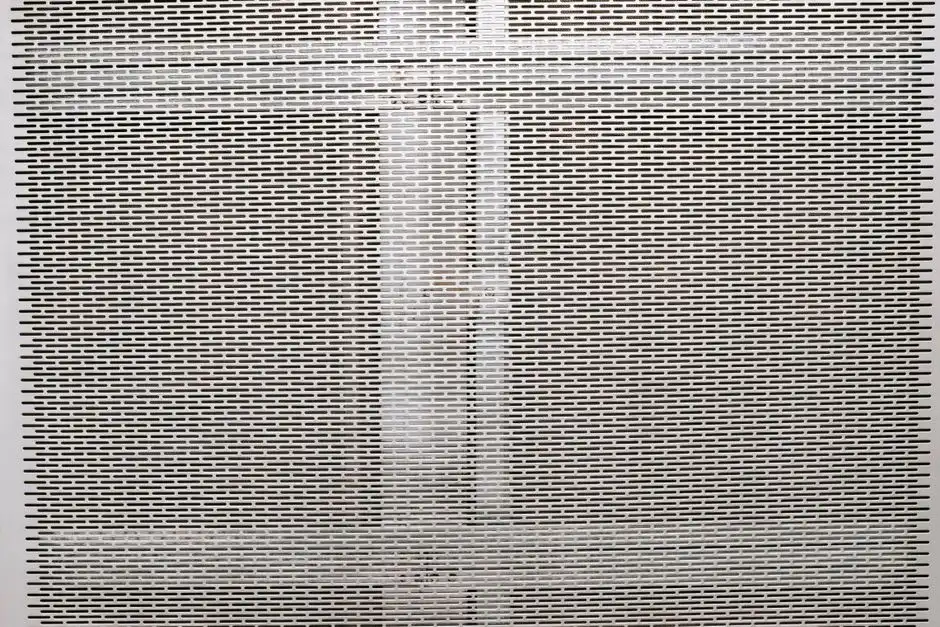
Submerged cylindrical wedgewire screens are the standard media-retention device in IFAS basins, and the Greensboro pilot confirmed them as the single most failure-prone component when not maintained (Hazen & Sawyer, 2026). CIP is triggered by rising dP across the screen, visible carryover of carriers into the effluent trough, or a mat of carriers accumulating against the screen face. The recommended CIP sequence is: isolate the IFAS cell by closing the inlet and outlet isolation gates, drain the cell to just above the screen crown, apply low-pressure water spray from inside the screen outward to dislodge biomass and grit, then reverse-flush with an air-water mix to clear blinded slots. Foam handling is a parallel problem: because free-floating media must be retained, natural foam traps form at the basin surface. The Greensboro O&M team addressed this with a low-cost retrofit — a vertical bar screen mounted near the water surface that retained media while passing foam out of the basin (Hazen & Sawyer, 2026). That retrofit works on any IFAS basin that struggles with surface foam. The first line of defense is upstream: pairing the IFAS with a rotary mechanical bar screen for IFAS preliminary treatment reduces the debris and fibrous material that otherwise loads the wedgewire slots and forces more frequent CIPs.
Biofilm, Mixing, and Aeration Maintenance
Healthy biofilm is thin, tan-to-brown, and evenly distributed across the carrier surface. A thick, black, patchy, or visibly sloughing biofilm is a warning sign — it usually indicates low DO, toxicity, or excessive loading on the IFAS cell. The Greensboro pilot quantified attached biomass weekly across all three cells using sample baskets, and that weekly biomass-accumulation measurement is the gold-standard practice any operator should adopt because biofilm thickness correlates directly with achievable nitrification rate (Hazen & Sawyer, 2026). Mixing is not optional in an IFAS basin: free-floating carriers will settle and channelize if the aeration grid does not keep them suspended, and settled media is dead media. Visual inspection of carrier distribution at multiple points across the basin surface — looking for exposed floor near the walls and piled carriers in corners — should be a daily item. Aeration-grid maintenance is a biological issue: any power interruption or diffuser failure that drops DO in an IFAS cell directly suppresses attached-growth activity. The cheapest insurance is a labeled sample basket of media left in each IFAS cell so the operator can pull, photograph, and compare biofilm condition against the previous week — a record that becomes diagnostic after three to six months.
IFAS Troubleshooting Matrix: Symptoms to Causes to Fixes
The matrix below condenses the most common IFAS operating symptoms into a one-page decision tool an O&M technician can use without paging a process engineer. Observe the symptom, walk down the probable cause column, then apply the listed fix. For facilities that want a deeper structured troubleshooting methodology for wastewater systems, the same symptom-cause-action logic applies across unit operations.
| Symptom | Probable Cause | Corrective Action |
|---|---|---|
| Media visible in effluent trough | Screen tear, slot blinding, or failed seal | Isolate cell, inspect screen panel, run CIP, replace damaged section |
| Loss of nitrification at constant load | Aeration grid partial failure or biofilm sloughing | Verify DO in each cell, inspect diffusers, review recent load/toxicity spikes |
| Excessive surface foam | Inadequate foam removal and high MLSS | Install or adjust vertical bar screen foam trap (Greensboro retrofit), review FOG upstream |
| Debris/floatables accumulating in first IFAS cell | Insufficient preliminary screening | Add or upgrade rotary bar screen, verify grit removal performance |
| Carrier media inventory declining | Washout through screens plus media attrition | Top up to design fill fraction (e.g., 35% K3), trace carryover path during high flows |
| High effluent TSS | Biofilm sloughing or foaming solids carryover | Check for toxicity events, verify wasting rate, inspect downstream clarifier |
Spare Parts, Documentation, and KPIs
Stocking the right spare parts on the shelf turns a two-day media-loss event into a same-day repair. The baseline spare-parts kit for an IFAS basin should include: at least one spare wedgewire screen panel matched to the installed slot opening, replacement carrier media in the correct type and size to refill to design fill fraction (K3-class for the Greensboro reference), two DO probe membranes ready for swap, a box of replacement diffuser membranes, screen wash pump seals and backwash valve rebuild kits, and a spare anoxic-zone mixer seal. Four KPIs are worth tracking on a monthly scorecard: percent media inventory versus design fill fraction, average screen dP, DO profile uniformity across all IFAS cells, and ammonia removal efficiency across the IFAS train (HydropureWater field data, 2026). A maintenance logbook that records every CIP, every media top-up volume, and every foam event is necessary, as patterns emerge after 6 to 12 months of consistent logging. Operators who want a real-time view of dP and DO trends should consider pairing the logbook with cloud-based monitoring of IFAS screen dP and DO profiles so deviations are caught between weekly rounds.
Frequently Asked Questions About IFAS Maintenance
How often should IFAS media retention screens be cleaned?
Screen cleaning should be condition-based, not calendar-based. Weekly dP readings are the trigger: when dP rises above roughly 0.3 m water column or shows a sustained upward trend, schedule a CIP on the affected cell. Waiting for a fixed monthly interval usually means cleaning screens that are still clean and missing the ones that are failing.
What is the right fill fraction for IFAS carriers?
Design fill fraction is media-specific and must be confirmed against the supplier's specification. The 35% K3 fill fraction used in the City of Greensboro pilot is a documented operating point, but moving to a different media geometry (K1, Biofilm-C, or sponge carriers) will change the design number. Operators should treat 35% as a reference, not a universal target, and top up to whatever the as-built design specifies.
How do you control foam in an IFAS basin?
Surface foam in an IFAS basin is best handled with a vertical bar screen mounted near the water surface that retains carriers while passing foam out of the basin — a retrofit the Greensboro O&M team developed and documented (Hazen & Sawyer, 2026). Pair the foam trap with WAS rate control and an FOG review upstream; high MLSS and surfactants both feed the foam layer.
What causes IFAS media loss and how is it prevented?
Media loss has three drivers: screen failure (tears, blinding, or seal failure), carryover during high hydraulic flows when the screen face is overloaded, and long-term attrition that breaks carriers into pieces small enough to pass the slot opening. Prevention is the four-tier program: weekly dP logging, monthly screen integrity inspection, annual CIP, and media inventory tracking against the design fill fraction so a top-up is triggered before nitrification capacity erodes.
Can IFAS nitrification recover after aeration failure?
Yes, and recovery is faster than in a conventional activated-sludge basin because the biofilm population protects a fraction of the nitrifiers from washout and short-term anoxia. A healthy IFAS basin typically returns to baseline ammonia removal within 24 to 72 hours of restoring aeration. Complete biofilm loss — for example, after a multi-day power outage with media left anoxic — requires reseeding with fresh carriers and re-establishing the attached population, which can take two to four weeks.
Frequently Asked Questions
How often should IFAS media retention screens be cleaned?
IFAS retention screens should be inspected and cleaned at least weekly, though frequency may increase to daily during high debris loading periods or seasonal high-flow events. Regular mechanical brushing or high-pressure water spraying is necessary to remove trapped hair, rags, and biofilm buildup that can cause head loss and screen blinding.
What is the right fill fraction for IFAS carrier media?
The optimal fill fraction typically ranges between 30% and 60% of the total basin volume, depending on the specific organic and nitrogenous loading requirements. It is critical not to exceed a 65% fill fraction to avoid excessive media-to-media abrasion, restricted hydraulic circulation, and potential oxygen transfer limitations caused by media packing.
How do you control foam in an IFAS basin?
Foam is primarily managed by maintaining the mean cell residence time (MCRT) and adjusting the aeration intensity to ensure adequate surface turbulence. If foaming persists, operators should verify that the food-to-microorganism (F/M) ratio is within the design range and consider the application of food-grade silicone-based antifoaming agents at a dosage rate of 1–5 ppm, ensuring that the chemical does not inhibit the nitrifying bacteria biofilm.
What causes IFAS media loss and how do you prevent it?
Media loss is most commonly caused by screen bypass, structural damage to retention sieves, or excessive hydraulic surges that overwhelm the screening system. Prevention requires daily integrity checks of all screen seals and gaskets, regular inspection for structural corrosion, and the installation of secondary redundant screening systems to capture media in the event of primary screen failure.
Can IFAS nitrification recover after an aeration failure?
Yes, IFAS systems are generally more resilient than suspended growth systems because the nitrifying bacteria are protected within the biofilm structure. Following an aeration failure, the system typically recovers full nitrification capacity within 48 to 96 hours, provided the biofilm has not been subjected to prolonged anaerobic conditions exceeding 12 hours, which could lead to biomass sloughing or the transition to denitrification.