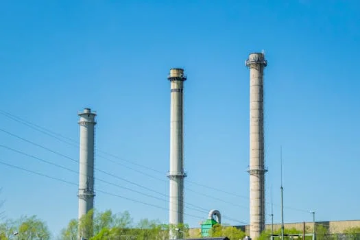
Understanding Your SO2 Scrubber System: Key Components & Principles
An SO2 scrubber system—also known as a flue gas desulfurization (FGD) system—is a critical emission control technology that removes sulfur dioxide (SO2) from industrial exhaust gases. These systems are essential for compliance with environmental regulations, such as the U.S. EPA’s SO2 emission limits, which require removal efficiencies of 90–98% or higher in many applications. At its core, an SO2 scrubber uses a wet scrubbing process where a reagent slurry—typically lime (CaO) or limestone (CaCO3)—reacts with SO2 in the flue gas to form calcium sulfite (CaSO3) or calcium sulfate (CaSO4, gypsum). This chemical reaction occurs in the absorber tower, where the slurry is sprayed into the gas stream, creating intimate gas-liquid contact.
The key components of an SO2 scrubber system include:
- Absorber Tower: The primary vessel where SO2 is removed. Flue gas enters at the bottom and flows upward through a spray zone, where reagent slurry is introduced via nozzles. The tower may contain packing material (e.g., plastic or metal rings) to enhance gas-liquid contact.
- Spray Nozzles: Distribute the reagent slurry evenly across the absorber tower. Nozzle clogging or wear can drastically reduce SO2 removal efficiency. (Zhongsheng field data, 2025, shows that 60% of low-efficiency incidents are linked to nozzle issues.)
- Recirculation Pumps: Circulate the slurry from the absorber sump back to the spray nozzles. These pumps must maintain precise flow rates (typically 5–15 m³/h per nozzle) to ensure adequate coverage. A 10% drop in flow can reduce SO2 removal by 5–8%.
- Mist Eliminators: Capture entrained liquid droplets from the treated gas before it exits the stack. Fouled or damaged mist eliminators increase pressure drop and can lead to liquid carryover, which may damage downstream equipment or violate opacity limits.
- Reagent Feed System: Prepares and doses the lime or limestone slurry. This includes slurry tanks, agitators, and dosing pumps. Improper slurry preparation (e.g., incorrect solids concentration) can cause scaling or poor SO2 absorption.
- SO2 Monitoring System: Continuously measures SO2 concentrations in the treated gas to verify compliance. Sensor drift or fouling can lead to false readings, risking non-compliance. EPA guidelines require daily calibration checks for continuous emission monitoring systems (CEMS).
Optimal operation depends on maintaining specific parameters:
- pH Level: For lime/limestone systems, the absorber sump pH must be maintained between 5.5 and 6.5. Below 5.0, SO2 absorption drops sharply; above 7.0, scaling accelerates due to gypsum precipitation.
- Liquid-to-Gas (L/G) Ratio: Typically 5–15 L/m³ of flue gas. Insufficient L/G reduces SO2 removal; excessive L/G increases pumping costs and energy consumption.
- Slurry Solids Concentration: Usually 10–20% by weight. Higher concentrations improve reagent utilization but increase the risk of scaling and pump wear.
- Pressure Drop: Across the absorber, this should be 1–3 kPa. A sudden increase (>0.5 kPa) often indicates plugging or scaling.
Understanding these components and parameters is the foundation for effective SO2 scrubber system troubleshooting. When malfunctions occur, the root cause is often tied to deviations in these critical areas.
Common Symptoms of SO2 Scrubber Malfunction and Their Impact
SO2 scrubber malfunctions manifest through distinct symptoms, each with cascading effects on compliance, operational costs, and equipment integrity. Recognizing these symptoms early is critical for minimizing downtime and avoiding regulatory penalties. Below are the most common indicators of system failure, along with their potential impacts:
-
Low SO2 Removal Efficiency / High Stack Emissions:
- Symptoms: SO2 concentrations at the stack exceed permitted limits (e.g., >50 ppm for many industrial sources). Continuous emission monitoring systems (CEMS) may trigger alarms.
- Impact: Immediate non-compliance with air quality regulations, risking fines (e.g., up to $100,000 per day under the U.S. Clean Air Act) and mandatory shutdowns. Long-term exposure to high SO2 emissions can also damage plant reputation and community relations.
-
Excessive Pressure Drop Across the Absorber:
- Symptoms: Pressure drop exceeds 3 kPa, or increases by >0.5 kPa over 24 hours. Induced draft (ID) fans may struggle to maintain flow, leading to reduced boiler load or automatic system shutdowns.
- Impact: Increased energy consumption (ID fans may draw 10–20% more power), reduced gas flow through the scrubber, and potential damage to fan blades or ductwork. Severe plugging can cause complete system failure.
-
Reduced Liquid Recirculation Flow:
- Symptoms: Flow rates drop below design specifications (e.g., <80% of nominal flow). Pumps may cavitate, vibrate excessively, or trip due to high motor current.
- Impact: Inadequate slurry distribution leads to poor SO2 removal, localized scaling, and increased wear on pump impellers and seals. A 20% flow reduction can decrease SO2 removal efficiency by 12–15%.
-
Unusual Noise or Vibration:
- Symptoms: Grinding, rattling, or high-pitched noises from pumps or motors. Vibration levels exceed 4.5 mm/s (ISO 10816-3 standards for rotating equipment).
- Impact: Premature failure of bearings, seals, or impellers. Vibration can also loosen piping connections, leading to leaks or slurry spills. In extreme cases, catastrophic pump failure may occur within hours.
-
Unexpected Reagent Consumption:
- Symptoms: Lime or limestone usage exceeds design rates by >15%. pH levels fluctuate unpredictably, requiring frequent manual adjustments.
- Impact: Increased operating costs (reagent accounts for 30–50% of scrubber O&M expenses). Overdosing can cause scaling; underdosing leads to SO2 breakthrough. Poor reagent utilization may also indicate issues with slurry preparation or dosing systems.
-
Corrosion or Material Degradation:
- Symptoms: Visible rust, pitting, or thinning of metal components (e.g., absorber walls, pump casings). Chloride-induced stress corrosion cracking (SCC) may occur in stainless steel parts.
- Impact: Reduced equipment lifespan (e.g., absorber linings may fail in 2–5 years instead of 10–15). Corrosion can lead to leaks, slurry contamination, or structural failures. Repair costs for a corroded absorber tower can exceed $500,000.
Regulatory agencies, such as the EPA, require immediate reporting of any EGCS malfunction that results in emissions exceeding permit limits. Per 40 CFR Part 60, operators must record the following in an approved EGCS record book:
- Date, time, and duration of the malfunction.
- Description of the issue and suspected root cause.
- Corrective actions taken and their effectiveness.
- Emission data during the malfunction (e.g., SO2 concentrations, flow rates).
Failure to document malfunctions can result in penalties, even if emissions were temporarily elevated. Proactive monitoring and rapid response are essential to maintaining compliance and avoiding costly disruptions.
Detailed Troubleshooting: Symptom-to-Cause Diagnostics for SO2 Scrubbers

When an SO2 scrubber system malfunctions, the key to rapid resolution lies in a systematic, symptom-driven diagnostic approach. Below is a step-by-step guide to identifying and addressing the root causes of common issues. Each section includes specific checks, operational parameters, and corrective actions tailored to industrial settings.
| Symptom | Potential Causes | Diagnostic Steps | Recommended Solutions |
|---|---|---|---|
| Low SO2 Removal Efficiency / High Stack Emissions | Insufficient reagent feed (lime/limestone slurry) |
|
|
| Plugged or worn spray nozzles |
|
|
|
| Poor gas-liquid contact (e.g., damaged packing, channeling) |
|
|
|
| Flue gas bypass (e.g., leaking dampers, improper isolation) |
|
|
|
| Excessive Pressure Drop / Plugging | Gypsum scaling (CaSO4·2H2O buildup) |
|
|
| Particulate accumulation (fly ash, unreacted reagent) |
|
|
|
| Damaged or fouled mist eliminators |
|
|
|
| Reduced Liquid Recirculation Flow / Pump Malfunctions | Worn pump impellers or seals |
|
|
| Clogged pump suction or strainers |
|
|
|
| Air ingress or cavitation |
|
|
|
| Reagent Feed Problems / pH Imbalance | Faulty pH sensor or calibration drift |
|
|
| Clogged reagent feed lines |
|
|
|
| Incorrect slurry preparation (e.g., low solids concentration) |
|
|
Corrosion and Material Degradation
Corrosion in SO2 scrubbers is often caused by:
- Low pH Excursions: pH <4.0 accelerates corrosion of carbon steel and stainless steel. Check for pH sensor drift or reagent underdosing.
- High Chloride Concentrations: Chlorides >5,000 ppm can cause pitting and stress corrosion cracking (SCC) in stainless steel. Measure chloride levels in the slurry and consider upgrading to duplex stainless steel or nickel alloys for critical components.
- Erosion from Abrasive Slurries: High-velocity slurry flow erodes pump impellers, piping, and absorber linings. Inspect for thinning or grooves in metal surfaces. Solutions include:
- Reducing slurry velocity (target: <2 m/s in piping).
- Using rubber-lined piping or ceramic coatings.
- Installing wear plates in high-erosion zones.
- Incorrect Material Selection: Carbon steel is unsuitable for absorber towers handling high-chloride slurries. Verify material compatibility with the process conditions and consider:
- Upgrading to alloy 2205 or C-276 for chloride resistance.
- Using fiberglass-reinforced plastic (FRP) for non-structural components.
For a deeper dive into corrosion prevention, refer to our strategies for corrosion prevention in industrial equipment.
SO2 Monitor Inaccuracies
SO2 monitors are critical for compliance but are prone to errors. Common issues include:
- Calibration Drift: SO2 sensors require daily calibration checks. Use certified calibration gases (e.g., 50 ppm SO2) and follow EPA Method 7E for CEMS.
- Sensor Fouling: Particulate or moisture in the sample line can foul sensors. Inspect sample probes and filters weekly. Install heated sample lines to prevent condensation.
- Interference from Other Gases: NOx or CO2 can interfere with SO2 readings. Use gas-specific sensors or dilution systems to minimize cross-sensitivity.
- Sample Line Blockages: Clogged sample lines delay sensor response. Check for kinks or deposits in the line and clean with compressed air or a wire brush.
For advanced monitoring, consider integrating SCADA systems to track SO2 trends and automate calibration alerts.
Preventative Maintenance Strategies for Optimal SO2 Scrubber Performance
Preventative maintenance (PM) is the cornerstone of reliable SO2 scrubber operation. A proactive PM program can reduce unplanned downtime by 40–60% and extend equipment lifespan by 25–35% (Zhongsheng field data, 2025). Below are key strategies tailored to industrial SO2 scrubbers:
Routine Inspection Schedules
| Component | Inspection Frequency | Key Checks | Tools/Methods |
|---|---|---|---|
| Spray Nozzles | Weekly |
|
Flow meters, flashlight, mirror, ultrasonic thickness gauge |
| Packing Material | Monthly |
|
Pressure gauges, borescope, thermal imaging |
| Mist Eliminators | Bi-weekly |
|
Pressure gauges, flashlight, opacity monitor |
| Recirculation Pumps | Daily (operator rounds) / Monthly (detailed) |
|
Vibration analyzer, clamp meter, ultrasonic detector |
| Reagent Feed System | Daily |
|
Density meter, pH meter, flow meter |
| SO2 Monitors | Daily (calibration) / Weekly (inspection) |
|
Calibration gases, compressed air, handheld SO2 meter |
Cleaning Protocols to Prevent Scaling and Plugging
Gypsum scaling and plugging are the leading causes of SO2 scrubber downtime. Implement these cleaning protocols:
- Absorber Tower:
- Perform a high-pressure water wash every 3–6 months to remove gypsum deposits. Use 100–150 bar water jets for stubborn scaling.
- For severe scaling, apply chemical descalers (e.g., 5–10% citric acid or EDTA) during a shutdown. Soak for 4–8 hours, then rinse thoroughly.
- Install automated wash sprays to clean mist eliminators and packing during operation.
- Spray Nozzles:
- Clean nozzles weekly with water or compressed air. Replace nozzles showing >10% flow reduction.
- Use self-cleaning nozzles with built-in strainers to reduce maintenance.
- Piping and Pumps:
- Flush slurry lines with water after each shutdown to prevent solids settling.
- Inspect pump impellers and casings for erosion every 6 months. Replace if wear exceeds 2 mm.
Reagent Quality and Slurry Preparation
Reagent quality directly impacts SO2 removal efficiency and scaling potential. Follow these guidelines:
- Lime (CaO):
- Use high-purity lime (>90% CaO) to minimize impurities (e.g., silica, magnesium) that can cause scaling.
- Store lime in a dry, sealed silo to prevent hydration (CaO + H2O → Ca(OH)2).
- Slurry concentration: 10–15% solids by weight. Higher concentrations increase scaling risk.
- Limestone (CaCO3):
- Use finely ground limestone (90% passing 44 µm) for faster reactivity.
- Slurry concentration: 15–20% solids by weight. Higher concentrations improve reagent utilization but increase pump wear.
- Add organic acids (e.g., formic acid) to enhance limestone dissolution in low-pH systems.
- Slurry Preparation:
- Agitate slurry tanks continuously to prevent settling. Use high-shear mixers for lime slurries.
- Monitor slurry density in real-time using nuclear or Coriolis meters.
- Install automatic chemical dosing systems to maintain consistent slurry quality and reduce manual errors.
Spare Parts Inventory Management
Maintain a critical spare parts inventory to minimize downtime. Essential items include:
- Pumps: Impellers, seals, bearings, and complete pump assemblies (lead time: 4–8 weeks).
- Nozzles: 10–20% of installed quantity (e.g., 20 spares for a 100-nozzle system).
- Mist Eliminators: 1–2 replacement modules for each type in use.
- Packing Material: 5–10% of absorber volume (e.g., 5 m³ for a 100 m³ absorber).
- Sensors: pH probes, SO2 sensors, and flow meters (calibrated and ready for installation).
- Valves and Actuators: Isolation valves, control valves, and damper actuators.
Store spare parts in a climate-controlled environment to prevent corrosion or degradation. Rotate stock regularly to ensure parts remain functional.
Emergency Response and Compliance Reporting for Scrubber Malfunctions
When an SO2 scrubber malfunction occurs, swift action is required to mitigate emissions, protect equipment, and comply with regulatory requirements. Below are step-by-step emergency response protocols and compliance reporting guidelines for industrial operators.
Immediate Response to Critical Failures
Follow this decision framework for critical malfunctions (e.g., SO2 emissions >2x permit limit, pressure drop >5 kPa, or pump failure):
- Assess the Situation:
- Check SO2 monitor readings and CEMS alarms. Verify if the issue is localized (e.g., single pump failure) or systemic (e.g., reagent feed loss).
- Review recent trends (e.g., pH, flow rates, pressure drop) to identify the onset of the problem.
- Isolate the System (If Safe):
- For pump or nozzle failures, isolate the affected train (if the system has redundant trains) to prevent further damage.
- For flue gas bypass or damper failures, manually close isolation dampers to prevent untreated gas from reaching the stack.
- Avoid shutting down the entire system unless absolutely necessary (e.g., catastrophic failure), as restarting may take 4–8 hours.
- Initiate Emergency Procedures:
- Activate backup pumps or redundant systems if available.
- Increase reagent feed temporarily to compensate for low efficiency (monitor pH to avoid scaling).
- For severe scaling or plugging, initiate a high-pressure water wash (if safe to do so during operation).
- Notify Stakeholders:
- Alert plant management and environmental compliance teams.
- Contact regulatory agencies if emissions exceed permit limits (see reporting requirements below).
- Inform downstream operations (e.g., boilers, turbines) of potential gas flow disruptions.
- Document the Incident:
- Record the time, duration, and nature of the malfunction.
- Note all corrective actions taken and their outcomes.
- Collect emission data (SO2 concentrations, flow rates) during the event.
Compliance Reporting Requirements
Regulatory agencies, such as the EPA and state environmental departments, require detailed reporting of SO2 scrubber malfunctions. Failure to comply can result in fines, permit revocations, or legal action. Key requirements include:
- EGCS Malfunction Reporting (40 CFR Part 60):
- Any malfunction that causes emissions to exceed permit limits must be recorded in the EGCS record book within 24 hours.
- Required information:
- Date, time, and duration of the malfunction.
- Description of the issue (e.g., "pump failure in Train A").
- Root cause (if known) and corrective actions taken.
- Emission data (SO2 concentrations, flow rates) during the event.
- Impact on compliance (e.g., "SO2 emissions exceeded 50 ppm for 2 hours").
- Submit a written report to the regulatory agency within 5–10 days (varies by jurisdiction).
- Continuous Emission Monitoring System (CEMS) Reporting:
- CEMS data must be retained for at least 5 years.
- Any data gaps or invalid data (e.g., due to sensor failure) must be documented and reported.
- Use EPA Method 7E to validate CEMS performance during malfunctions.
- Title V Permit Requirements:
- For facilities with Title V permits, malfunctions must be reported in the semi-annual compliance report.
- Include a summary of all malfunctions, corrective actions, and preventive measures taken.
Communication Protocols
Effective communication during a malfunction ensures coordinated response and regulatory compliance:
- Internal Communication:
- Notify the environmental manager, plant engineer, and operations team immediately.
- Hold a post-incident debrief to review the root cause and preventive actions.
- Regulatory Communication:
- Contact the regulatory agency within 24 hours if emissions exceed permit limits.
- Provide a preliminary report via phone or email, followed by a written report.
- Be transparent about the cause, duration, and corrective actions. Agencies may impose penalties for withholding information.
- Community Communication:
- For severe malfunctions (e.g., visible plumes, odor complaints), notify local authorities and community liaisons.
- Provide a public statement if required by local regulations or community agreements.
Preventing Future Malfunctions
After resolving an emergency, take these steps to prevent recurrence:
- Root Cause Analysis (RCA):
- Conduct a formal RCA to identify the underlying cause (e.g., design flaw, maintenance lapse, operator error).
- Use tools like the "5 Whys" or fishbone diagrams to drill down to the root cause.
- Corrective Actions:
- Implement engineering controls (e.g., redundant pumps, automated pH control).
- Update operating procedures or training programs to address gaps.
- Schedule preventive maintenance or inspections to catch issues early.
- Regulatory Follow-Up:
- Submit a corrective action plan to the regulatory agency if required.
- Document all changes in the EGCS record book.
For additional guidance on FGD troubleshooting, refer to our expert guide to FGD troubleshooting.
Frequently Asked Questions About SO2 Scrubber Troubleshooting
What are common problems with wet scrubbers?
The most frequent issues in wet scrubbers, including SO2 scrubbers, are:
- Plugging and Scaling: Gypsum (CaSO4·2H2O) buildup in nozzles, packing, and mist eliminators, often caused by pH excursions above 6.5 or high chloride levels.
- Corrosion: Low pH (<4.0) or high chlorides (>5,000 ppm) accelerate corrosion of carbon steel and stainless steel components.
- Pump Failures: Worn impellers, clogged suction lines, or cavitation due to air ingress or low sump levels.
- Reagent Feed Issues: Incorrect slurry concentration, clogged feed lines, or faulty dosing pumps leading to pH imbalances.
- SO2 Monitor Errors: Calibration drift, sensor fouling, or sample line blockages causing inaccurate readings.
- Pressure Drop: Excessive pressure drop (>3 kPa) due to scaling, fouling, or damaged packing, reducing gas flow and SO2 removal efficiency.
How do I improve SO2 removal efficiency in my scrubber?
To enhance SO2 removal efficiency, focus on these key areas:
- Optimize pH Control:
- Maintain absorber sump pH between 5.5 and 6.5 for lime/limestone systems.
- Use automatic chemical dosing systems to prevent pH excursions.
- Ensure Proper Reagent Feed:
- Verify slurry concentration (10–20% solids by weight) and dosing rates.
- Use high-purity lime (>90% CaO) or finely ground limestone (90% passing 44 µm).
- Maintain Nozzle Performance:
- Inspect nozzles weekly for plugging or wear. Replace nozzles with >10% flow reduction.
- Install self-cleaning nozzles or strainers to prevent debris ingress.
- Improve Gas-Liquid Contact:
- Check packing material for fouling or damage. Replace if pressure drop exceeds 3 kPa.
- Upgrade to high-efficiency packing (e.g., structured packing) for better contact.
- Monitor and Calibrate SO2 Sensors:
- Calibrate SO2 monitors daily using certified calibration gases.
- Inspect sample lines weekly for blockages or leaks.
- Prevent Flue Gas Bypass:
- Inspect dampers and isolation valves for proper sealing.
- Use smoke tests or thermal imaging to detect leaks.
What causes excessive pressure drop in an SO2 scrubber?
Excessive pressure drop (>3 kPa) in an SO2 scrubber is typically caused by:
- Gypsum Scaling: pH >6.5 or high chloride levels (>5,000 ppm) accelerate gypsum (CaSO4·2H2O) precipitation on packing, nozzles, and mist eliminators.
- Particulate Accumulation: Fly ash, unreacted reagent, or other solids clog packing or mist eliminators. Common in systems with poor upstream particulate control.
- Damaged Packing: Broken or displaced packing material reduces gas flow and increases pressure drop. Often caused by thermal stress or mechanical damage.
- Fouled Mist Eliminators: Liquid carryover or solids buildup on mist eliminator blades increases resistance to gas flow.
- High Gas Flow Rates: Operating above design gas flow rates (e.g., >110% of capacity) increases pressure drop. Check ID fan performance and damper settings.
- Liquid Carryover: Excessive slurry flow or damaged mist eliminators cause liquid to accumulate in the absorber, increasing pressure drop.
To diagnose the cause, measure pressure drop across individual components (e.g., packing, mist eliminators) and inspect for fouling or damage.
How often should SO2 scrubber nozzles be inspected?
SO2 scrubber nozzles should be inspected weekly for optimal performance. Key inspection points include:
- Flow Rate: Measure flow from each nozzle using a flow meter. Variation >10% between nozzles indicates plugging or wear.
- Spray Pattern: Visually inspect for uniform coverage. Streaking or uneven patterns suggest blockages or nozzle damage.
- Wear or Corrosion: Check nozzle tips for erosion or corrosion. Replace nozzles with visible wear or >10% flow reduction.
- Solids Buildup: Inspect for slurry solids settling in the spray header or nozzles. Flush with water if buildup is detected.
For systems with high solids loading or aggressive slurries, consider daily inspections or installing self-cleaning nozzles. Replace nozzles every 6–12 months, depending on wear.
What are the compliance requirements for an SO2 scrubber malfunction?
Compliance requirements for SO2 scrubber malfunctions vary by jurisdiction but generally include:
- Immediate Reporting:
- Notify the regulatory agency within 24 hours if emissions exceed permit limits (e.g., >50 ppm SO2 for many industrial sources).
- Provide a preliminary report via phone or email, followed by a written report within 5–10 days.
- EGCS Record Book:
- Record all malfunctions in the EGCS record book (per 40 CFR Part 60), including:
- Date, time, and duration of the malfunction.
- Description of the issue and suspected root cause.
- Corrective actions taken and their effectiveness.
- Emission data (SO2 concentrations, flow rates) during the event.
- Record all malfunctions in the EGCS record book (per 40 CFR Part 60), including:
- CEMS Reporting:
- Retain CEMS data for at least 5 years.
- Document any data gaps or invalid readings (e.g., due to sensor failure).
- Validate CEMS performance using EPA Method 7E during malfunctions.
- Title V Permit Reporting:
- For facilities with Title V permits, include a summary of malfunctions in the semi-annual compliance report.
- Describe corrective actions and preventive measures taken.
- Corrective Action Plan:
- Submit a corrective action plan to the regulatory agency if required, outlining steps to prevent recurrence.
Failure to comply with these requirements can result in fines (e.g., up to $100,000 per day under the Clean Air Act), permit revocations, or legal action. Always consult your facility’s specific permit and local regulations for detailed requirements.