Photovoltaic Wastewater Treatment Project: 2025 Engineering Specs, Hybrid System Design & 99% Recovery Blueprint
Photovoltaic (PV) wastewater treatment projects combine solar energy with industrial wastewater systems to reduce energy costs by up to 40% while meeting strict discharge standards for fluorine (99% removal via chemical precipitation) and ammonia (95%+ removal via biological treatment). In 2025, hybrid systems integrating dissolved air flotation (DAF), MBR membranes, and on-site solar PV arrays are achieving 99% water recovery and $0.50–$1.20/m³ operational savings, per EPA and Gradiant case data. This guide provides engineering specs, process design blueprints, and cost-optimized solar integration strategies for PV fabs and other high-energy facilities.
Why PV Wastewater Treatment Projects Are Shifting to Solar Power
Wastewater treatment accounts for up to 30% of a typical PV fab’s energy bill, contributing to the estimated $4 billion annual U.S. utility spend for water and wastewater operations, per EPA 2024 data. This substantial energy burden, coupled with increasing regulatory scrutiny on discharge quality, is driving a rapid shift towards renewable energy integration in industrial wastewater treatment. Solar PV systems offer a compelling solution, capable of reducing grid dependency by 35–60% in wastewater treatment plants, often with payback periods ranging from 5 to 7 years, according to Enfinity Corporation benchmarks.
Global regulatory frameworks, such as China’s GB 31573-2015 and the EU Industrial Emissions Directive 2010/75/EU, are continually tightening discharge limits for critical contaminants like fluorine and ammonia. These stringent standards necessitate advanced treatment technologies that are often energy-intensive. Integrating solar power not only helps meet sustainability goals but also provides a buffer against volatile energy prices, securing long-term operational stability.
A notable real-world example demonstrates this impact: a 100 m³/h PV wastewater plant in India successfully cut its energy costs by 42% after installing a 500 kW solar array, as documented in a Gradiant case study. This significant reduction highlights the immediate financial benefits of solar integration, making photovoltaic wastewater treatment projects a strategic imperative for facilities aiming for both environmental compliance and economic efficiency.
Photovoltaic Wastewater Contaminant Profiles: Engineering Specs for Fluorine, Ammonia, and Heavy Metals

Effective treatment of PV manufacturing wastewater requires a precise understanding of its unique contaminant profile, which typically includes high concentrations of fluorine, ammonia, and various heavy metals. Fluorine-rich wastewater, often present at concentrations of 50–500 mg/L from etching processes, is predominantly treated via chemical precipitation using calcium hydroxide (Ca(OH)₂) or calcium chloride (CaCl₂). This method consistently achieves 92–98% removal efficiency, with optimal performance requiring pH adjustment to a range of 8.5–9.5, as supported by scientific literature (Top 2 data). For detailed fluoride wastewater treatment engineering specs and hybrid system design, further resources are available.
Ammonia and nitrate-rich wastewater, with influent concentrations typically ranging from 100–1,000 mg/L, demands robust biological treatment. Anaerobic/Anoxic/Oxic (A/O) or MBR membrane bioreactor for ammonia and nitrate polishing systems are highly effective, removing over 95% of these nitrogenous compounds. Optimal denitrification performance in biological processes requires a carbon-to-nitrogen (C:N) ratio greater than 4:1 and hydraulic retention times (HRT) between 12 and 24 hours. Heavy metals, such as nickel and copper, are also common in PV wastewater. High-efficiency DAF system for fluorine and heavy metal removal can remove over 90% of suspended metals, while reverse osmosis (RO) membranes are used for polishing, reducing concentrations to below 0.1 mg/L for potential water reuse applications. For further insights into RO system engineering specs for water reuse in PV wastewater projects and water reuse and ZLD strategies for PV wastewater projects, refer to dedicated guides.
The following table summarizes typical contaminant loads and treatment targets for PV wastewater:
| Contaminant | Influent Range (mg/L) | Effluent Standard (mg/L) | Treatment Process | Removal Efficiency |
|---|---|---|---|---|
| Fluorine (F-) | 50 – 500 | <10 (China/EU), <4 (U.S.) | Chemical Precipitation (Ca(OH)₂/CaCl₂) | 92 – 98% |
| Ammonia Nitrogen (NH₃-N) | 100 – 1,000 | <15 (China), <10 (EU) | Biological Treatment (A/O, MBR) | 95%+ |
| Nitrate Nitrogen (NO₃-N) | 50 – 500 | <20 (EU), <50 (U.S.) | Biological Denitrification | 90%+ |
| Copper (Cu) | 1 – 20 | <0.1 | DAF, Chemical Precipitation, RO | 90 – 99%+ |
| Nickel (Ni) | 1 – 15 | <0.1 | DAF, Chemical Precipitation, RO | 90 – 99%+ |
| Total Suspended Solids (TSS) | 100 – 500 | <10 | Screening, DAF, MBR | 95%+ |
Hybrid System Design: Combining Solar PV with Chemical and Biological Treatment for PV Wastewater
Designing a hybrid photovoltaic wastewater treatment system involves integrating solar energy generation with a multi-stage contaminant-specific treatment process to achieve both high removal efficiencies and significant energy savings. For solar PV sizing, industrial wastewater plants typically require 0.5–1.2 kW of solar capacity per cubic meter per hour (kW/m³) of treated water. This means a 100 m³/h PV wastewater plant would necessitate a solar array with an installed capacity ranging from 50 kW to 120 kW, based on EPA Region 9 benchmarks.
Energy storage is a critical component for ensuring continuous operation, particularly during nighttime or periods of low solar irradiance. Lithium-ion batteries, providing 4–6 hours of storage at an 80% depth of discharge, are commonly specified. While energy storage adds 15–25% to the overall CAPEX, it significantly enhances grid independence and operational reliability. Alternatively, a robust grid tie-in system can supplement power during off-peak solar periods, often utilizing net metering policies to offset energy costs.
A typical process flow for a hybrid PV wastewater treatment system targeting common PV fab contaminants would be: 'Influent → Screening → DAF (for initial solids and high-efficiency DAF system for fluorine and heavy metal removal) → Chemical Precipitation (for fluorine removal, often with a PLC-controlled chemical dosing system for pH adjustment and precipitation) → A/O Bioreactor (for ammonia and nitrate removal) → MBR membrane bioreactor for ammonia and nitrate polishing (for advanced polishing and solids separation) → Solar PV Array (providing primary energy supply to all treatment stages) → Effluent'. Energy recovery points, such as methane capture from anaerobic digestion (if applicable) or heat recovery, can further enhance the system's overall energy balance.
Consider a 200 m³/h PV wastewater plant, which might consume an average of 120 kWh/h for its treatment processes. A strategically sized 600 kW solar array could effectively offset 50% or more of this grid demand, significantly reducing operational expenses. The integration of the solar PV array directly supplies power to pumps, blowers, mixers, and control systems throughout the treatment train, creating a self-sufficient energy ecosystem.
Hybrid PV Wastewater Treatment System Process Flow (Diagram Description):
- Influent: Raw wastewater enters the system.
- Screening: Removes large debris and suspended solids.
- DAF Unit: Dissolved air flotation for suspended solids, heavy metals, and initial fluoride precipitation.
- Chemical Dosing System: Precise addition of coagulants, flocculants, and pH adjustment chemicals for fluoride and heavy metal precipitation.
- A/O Bioreactor: Aerobic/Anoxic zones for biological nitrification and denitrification, primarily for ammonia and nitrate removal.
- MBR Unit: Membrane bioreactor for advanced biological treatment, superior solids separation, and effluent polishing.
- Treated Water Storage: Holds treated water for discharge or further reuse.
- Solar PV Array: On-site photovoltaic panels generating electricity.
- Inverters & Electrical Panel: Converts DC solar power to AC and distributes it to treatment units.
- Battery Storage: Stores excess solar energy for use during low sunlight or peak demand.
- Grid Tie-in: Connection to the utility grid for supplemental power or net metering.
- Effluent: Discharged water meeting regulatory standards, with optional RO for water reuse.
Solar PV Integration: Engineering Specs for On-Site Energy Generation and Storage
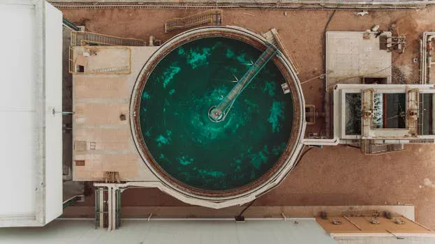
Effective solar PV integration into industrial wastewater treatment plants requires meticulous engineering to match energy generation with demand, ensuring reliability and cost-efficiency. Monocrystalline solar panels, with typical efficiencies ranging from 20–22%, are generally preferred over polycrystalline panels (15–18% efficiency) for wastewater facilities, especially where land availability is limited, due to their higher power output per unit area. This allows for a smaller footprint while maximizing energy capture.
Inverter sizing is crucial for system stability and longevity. It is standard practice to oversize inverters by 10–15% relative to the nominal solar array capacity to effectively handle peak loads and optimize energy conversion during varying irradiance conditions. For instance, a 100 kW solar array would ideally be paired with 110–115 kW of inverter capacity. Battery storage systems, typically lithium-ion due to their higher energy density and longer cycle life, are designed to provide 4–6 hours of backup power at an 80% depth of discharge (DoD). Lithium-ion batteries offer a lifespan of 10–15 years, significantly outperforming lead-acid alternatives (5–7 years).
Grid tie-in with net metering capabilities can substantially reduce the payback period of a solar PV investment by 20–30%, allowing facilities to sell excess generated electricity back to the grid. However, regulatory hurdles for grid interconnection and net metering policies vary significantly by region, from China’s '531 Policy' impacting solar development to diverse state-level incentives in the U.S. and federal tax credits (ITC). Understanding these local regulations is critical for project financial modeling.
The following table provides typical sizing parameters and estimated CAPEX for solar PV systems integrated with various wastewater plant capacities:
| Plant Capacity (m³/h) | Solar Array Size (kW) | Battery Storage (kWh) | Inverter Size (kW) | Estimated CAPEX (USD) |
|---|---|---|---|---|
| 50 | 25 – 60 | 100 – 240 | 30 – 70 | $75,000 – $180,000 |
| 100 | 50 – 120 | 200 – 480 | 60 – 140 | $150,000 – $360,000 |
| 200 | 100 – 240 | 400 – 960 | 120 – 280 | $300,000 – $720,000 |
| 500 | 250 – 600 | 1000 – 2400 | 300 – 700 | $750,000 – $1,800,000 |
Cost Breakdown and ROI: 2025 CAPEX/OPEX for Photovoltaic Wastewater Treatment Projects
Evaluating the financial viability of photovoltaic wastewater treatment projects necessitates a detailed breakdown of both capital expenditures (CAPEX) and operational expenditures (OPEX), alongside robust return on investment (ROI) analysis. In 2025, the CAPEX for a comprehensive hybrid treatment system, including DAF, MBR, and solar PV integration, typically ranges from $1,200–$2,500 per cubic meter per hour of plant capacity. Solar PV integration specifically adds an estimated 20–30% to the base CAPEX of a conventional treatment system, reflecting the cost of panels, inverters, mounting structures, and battery storage.
Operational expenditures show a marked advantage for solar-powered systems. While grid-only systems incur OPEX of $0.80–$1.50/m³, solar-powered systems can achieve significant savings, bringing OPEX down to $0.30–$0.80/m³. This translates to annual operational savings of 30–50%, primarily driven by reduced electricity bills and lower carbon taxes. The return on investment for the solar PV integration component typically falls within 5–7 years, while the full hybrid system (including advanced treatment upgrades) generally sees an ROI of 8–10 years.
Further enhancing financial attractiveness are various federal and state incentives. Programs such as the U.S. Investment Tax Credit (ITC) offering 30% for solar installations, or China’s 'Golden Sun' program, can reduce the initial CAPEX by 25–40%. These incentives are critical for improving project economics and accelerating payback periods. Procurement teams must account for these subsidies when developing their financial models.
The following table provides a comparative financial overview for solar-powered versus grid-powered PV wastewater treatment systems:
| System Size (m³/h) | CAPEX (Solar-Powered) | OPEX (Solar-Powered, $/m³) | CAPEX (Grid-Powered) | OPEX (Grid-Powered, $/m³) | Annual Savings (USD) | Payback Period (Years) |
|---|---|---|---|---|---|---|
| 50 | $60,000 – $125,000 | $0.35 – $0.80 | $50,000 – $100,000 | $0.80 – $1.50 | $10,000 – $25,000 | 6 – 9 |
| 100 | $120,000 – $250,000 | $0.30 – $0.70 | $100,000 – $200,000 | $0.75 – $1.40 | $25,000 – $60,000 | 5 – 8 |
| 200 | $240,000 – $500,000 | $0.30 – $0.65 | $200,000 – $400,000 | $0.70 – $1.30 | $50,000 – $120,000 | 5 – 7 |
| 500 | $600,000 – $1,250,000 | $0.30 – $0.60 | $500,000 – $1,000,000 | $0.65 – $1.20 | $120,000 – $300,000 | 5 – 7 |
Step-by-Step Project Implementation: From Feasibility Study to Commissioning
Successful implementation of a photovoltaic wastewater treatment project follows a structured, multi-phase approach, beginning with thorough assessment and culminating in integrated system commissioning. The initial feasibility study typically spans 4–6 weeks and is critical for defining project scope and viability. This phase involves assessing influent contaminant loads, existing energy consumption patterns, and the site's solar potential, often guided by resources like EPA’s 'Solar Energy for Water Utilities' guide (Top 1). Key deliverables include a detailed technical report and preliminary financial projections.
The design phase, lasting 8–12 weeks, focuses on engineering the hybrid treatment and solar PV system. This includes selecting specific treatment technologies (e.g., DAF, MBR, chemical dosing), sizing the solar array, inverters, and battery storage, and developing detailed process flow diagrams and electrical schematics. Concurrently, environmental impact assessments and grid interconnection permits must be obtained, which can be a complex and time-consuming process depending on local regulations.
Procurement for the project typically takes 12–16 weeks. During this stage, equipment such as DAF units, MBR modules, solar panels, inverters, and chemical dosing systems are sourced. Prioritizing turnkey suppliers can streamline this process, ensuring compatibility and faster deployment. Construction follows, generally requiring 16–24 weeks. It is often strategic to install the wastewater treatment system components first, allowing for initial testing, before integrating the solar array and its associated electrical infrastructure. Commissioning should occur in stages: individual treatment units, then the solar power system, and finally, the complete integrated hybrid system, ensuring each component functions optimally before full system operation.
Common pitfalls during implementation include underestimating battery storage needs for continuous operation, failing to accurately account for local solar irradiance data which can lead to undersized arrays, or neglecting to size inverters appropriately for peak electrical loads, potentially causing system inefficiencies or shutdowns. Diligent planning and adherence to engineering best practices are essential to mitigate these risks and ensure a successful photovoltaic wastewater treatment project.
Frequently Asked Questions
This section addresses common technical and financial questions regarding photovoltaic wastewater treatment projects.
What is the typical payback period for a solar-powered PV wastewater treatment system?
The typical payback period for the solar PV integration component of a PV wastewater treatment system ranges from 5 to 7 years, depending on local energy costs, available incentives, and system size.
Can solar PV power a wastewater treatment plant 24/7?
No, solar PV alone cannot power a wastewater treatment plant 24/7. Continuous operation requires either a grid tie-in to draw power during nighttime or extended periods of low sunlight, or a sufficiently sized battery storage system to cover off-peak hours.
What are the discharge limits for fluorine and ammonia in PV wastewater?
Discharge limits for fluorine in PV wastewater typically range from <10 mg/L in regions like China and the EU, to stricter limits of <4 mg/L in some U.S. jurisdictions. For ammonia, common limits are <15 mg/L in China and <10 mg/L in the EU.
How much space is needed for a solar array at a 100 m³/h wastewater plant?
A 100 m³/h wastewater treatment plant requiring a 500 kW solar system would typically need approximately 500–1,200 m² of land for the solar array, depending on the efficiency of the solar panels and mounting configuration (e.g., fixed-tilt vs. tracking).
What are the maintenance requirements for solar-powered wastewater systems?
Maintenance for solar panels generally involves quarterly cleaning to remove dust and debris, ensuring optimal energy capture. For the wastewater treatment equipment (e.g., DAF, MBR), weekly inspections, routine sensor calibration, and periodic membrane cleaning or replacement are standard to maintain efficiency and compliance.