wet fgd scrubber troubleshooting guide: system fundamentals
A wet fgd scrubber troubleshooting guide starts with the process state, not a single alarm. Wet FGD systems remove sulfur dioxide (SO₂) by contacting flue gas with limestone or lime slurry in an absorber tower. A reliable diagnosis correlates SO₂ emissions, absorber pressure drop, slurry pH, liquid-to-gas ratio, reagent feed, pump condition, mist washing, and wastewater blowdown before changing one setpoint.
Wet FGD systems use an absorber tower, slurry pumps, atomizer wheels or spray nozzles, mist eliminators, reaction tanks, and reagent preparation equipment. The absorber creates gas-liquid contact; the pumps maintain circulation; the nozzles or wheels distribute the slurry; and the mist eliminators retain entrained droplets before the cleaned gas leaves the tower. These functions must be considered together because a restriction or chemistry upset in one area can appear as an emission, flow, or pressure symptom elsewhere.
The core reactions remain useful for field diagnosis. Sulfur dioxide dissolves in the aqueous phase and reacts with calcium hydroxide (Ca(OH)₂) to form calcium sulfite: Ca(OH)₂ + SO₂ → CaSO₃ + H₂O. With air sparging, calcium sulfite can oxidize to calcium sulfate, commonly called gypsum: CaSO₃ + ½O₂ → CaSO₄. The flue gas composition, reagent quality, slurry residence time, oxidation state, and blowdown rate determine whether those reactions support absorption or produce deposits.
The original operating envelope of slurry pH, typically 5.0 to 6.0, remains a practical troubleshooting range for the system described here. According to the U.S. EPA lime/limestone FGD inspection manual, fresh limestone slurry entering the absorber is commonly controlled at 5.5 to 6.0, while spent limestone slurry can leave at 4.5 to 5.0. Treat those values as process-specific control points, not a universal replacement for the equipment design basis.
According to the U.S. EPA wet-scrubber monitoring guidance, pressure differential, liquid flow rate, and scrubber-liquid outlet concentration are primary performance indicators; gas flow, neutralizing chemical feed, outlet temperature, pH, specific gravity, and makeup or blowdown rates add diagnostic context. This measurement set is more useful than changing reagent feed from an isolated SO₂ reading.
Common flue gas desulfurization problems and their symptoms
Flue gas desulfurization troubleshooting becomes faster when symptoms are grouped by measurement. Rising SO₂ at the stack usually points to insufficient alkalinity, falling slurry pH, low liquid-to-gas ratio, poor spray coverage, high inlet loading, or restricted gas-liquid contact. Verify the CEMS signal and the inlet load before assuming that the absorber chemistry alone has failed.
Higher pressure drop or lower gas flow indicates a restriction in the absorber, spray zone, packing or trays, mist eliminator, duct, or downstream reheat path. A pressure trend is particularly valuable: a gradual increase often indicates scale or solids deposition, while an abrupt change can indicate a collapsed component, plugged nozzle bank, fan change, or instrument fault. EPA guidance also identifies inadequate liquid flow, re-entrainment, poor gas-liquid contact, corrosion, and plugged nozzles or mist eliminators as recurring wet-scrubber operating problems.
Knocking noise, unstable discharge pressure, or seal leakage points toward a slurry-pump problem. Uneven tank level, overflow, or a fast change in density can indicate makeup-water, reagent-feed, thickener, dewatering, or blowdown problems. Pitting or thinning in wet ductwork, absorber shells, or pump parts indicates corrosion risk, especially where wet/dry cycling concentrates chloride and acidic species.
Use the same evidence discipline applied in claus plant troubleshooting: confirm the instrument, compare the value with the design trend, inspect the physical equipment, and change one controllable variable at a time. A symptom is a starting point, not proof of a root cause.
Deep dive: troubleshooting specific FGD equipment failures
FGD equipment failures should be investigated from the symptom toward the process mechanism. HydropureWater's FGD Scrubber Systems are represented by the same engineering checks used for any wet absorber: establish gas load, liquid flow, slurry chemistry, solids behavior, mechanical condition, and the history of cleaning or maintenance before selecting a repair.
wet limestone fgd system scaling solutions
Wet limestone fgd system scaling solutions begin with controlling supersaturation, pH, solids concentration, and the residence time available for crystal growth. High slurry temperatures, often exceeding 140°F (60°C), accelerate precipitation of calcium salts on atomizer wheels and spray nozzles. High calcium content, insufficient blowdown, or poor reagent preparation raises the concentration of scale precursors and narrows the operating margin.
The U.S. EPA inspection manual describes calcium sulfite as a softer scale and calcium sulfate or gypsum as a harder deposit that can be difficult to remove, particularly when excess reagent is carried into the mist eliminator. The manual also connects scaling control with liquid-to-gas ratio and pH. In practice, operators should trend pH, specific gravity, solids, chloride, calcium, sulfate, and blowdown together rather than chase a single laboratory result.
Start with a controlled blowdown strategy that limits dissolved solids and suspended particles without destabilizing the reaction tank. Confirm limestone fineness, reagent feed calibration, mixing, and slurry density. Inspect spray patterns and nozzle or wheel surfaces during a planned outage. Mechanical cleaning or compatible chemical washing can restore capacity; persistent deposits may justify larger-orifice nozzles, a different atomizer design, or a coating selected for the actual chemistry.
Keep the original pH warning in view. Low slurry pH below 5.0 can increase corrosion and reduce absorption, while high pH can increase calcium sulfite precipitation. The practical action is a small, documented setpoint change with simultaneous monitoring of SO₂ removal, pressure drop, pump load, and solids behavior.
fgd slurry pump cavitation causes and fixes
fgd slurry pump cavitation causes and fixes are identified through suction conditions, pump position on its performance curve, slurry properties, and the sound and pressure trend. Cavitation occurs when local liquid pressure falls below vapor pressure, forming bubbles that collapse near the impeller. In FGD service, inadequate suction head, a restricted suction line, high viscosity, excessive flow, or an incorrect impeller can create the condition.
Separate cavitation from abrasion and corrosion. Cavitation produces rattling or knocking, fluctuating discharge pressure, vibration, and pitted hydraulic surfaces. Abrasive wear from fine gypsum crystals and unreacted limestone enlarges clearances and erodes the impeller, casing, and liners. Low slurry pH can accelerate corrosion, especially where the selected metal or rubber lining does not match the process chemistry.
Check the suction strainer, tank level, suction-line valves, entrained air, slurry temperature, solids concentration, and actual flow against the pump curve. Do not raise speed simply to recover a falling discharge pressure; that can move the pump farther from its best efficiency point. Verify the duty point after any process change, inspect wear parts and seals, and record vibration and motor load before and after correction.
Material selection should follow particle size distribution, solids concentration, abrasiveness, chloride exposure, and pH. High-chrome iron alloys or specialized rubber linings can be appropriate for different wear zones. The right choice is service-specific; a harder material does not correct a starved suction line or an oversized operating point.
absorber tower plugging in flue gas desulfurization
Absorber tower plugging in flue gas desulfurization is usually indicated by rising gas-side pressure drop, declining gas flow, uneven spray coverage, or a loss of SO₂ removal at unchanged reagent feed. Plugging can occur on trays, packing, spray headers, nozzles, ducts, or mist eliminator passages. Over-saturated slurry, poor reagent distribution, particulate carryover, and weak wash coverage are common contributors.
Compare the current pressure drop with the clean baseline and inspect the trend by load. EPA’s FGD inspection manual states that an increase across the absorber or mist eliminator is commonly associated with plugging or scaling, while high gas flow and high slurry flow can also compress the gas path. That distinction matters: reducing liquid flow may lower pressure drop briefly while worsening SO₂ absorption.
Confirm the L/G ratio, nozzle pressure, spray pattern, absorber level, slurry density, pH profile, and solids removal. Inspect upstream particulate control and the wet/dry interface for deposits. Restore distribution before adding anti-scalant. Any chemical additive must be compatible with the reagent, gypsum quality, wastewater treatment, elastomers, and downstream discharge requirements.
Use an outage plan that isolates the affected section, removes deposits safely, checks nozzle and header alignment, and verifies free passage before restart. After the restart, trend pressure drop, gas flow, liquid flow, SO₂, and mist carryover together. A clean tower that is operated with unstable chemistry will plug again.
fgd mist eliminator fouling prevention
fgd mist eliminator fouling prevention depends on controlling droplet carryover and maintaining the wash system. Mist eliminators capture slurry droplets, but solids in those droplets can dry into a crust on blades or vanes. High gas velocity, foaming, excess slurry carryover, blocked wash nozzles, low wash flow, and high dissolved salts in recycled water all increase fouling risk.
The U.S. EPA inspection manual recommends checking wash-water quality, wash duration, wash frequency, wash rate, pressure drop, slurry chemistry, relative saturation, and blade condition when fouling persists. The manual also notes that recycled water with high dissolved solids can promote deposits on mist eliminator surfaces and wash lances. Use fresh or suitably clarified water where the water balance and permit allow it.
Begin with the least disruptive correction: verify automatic and manual wash operation, clear wash nozzles and piping, and extend wash duration before increasing wash rate. Inspect for broken, deformed, melted, or corroded blades. If pressure drop remains high, reduce absorber recirculation slurry pH incrementally while watching SO₂ removal, then schedule an outage for deposit removal and chemical analysis.
Do not target the sibling phrase fgd mist eliminator scaling as a separate topic here. Use that page for the narrower scaling intent, while this article keeps fouling prevention tied to absorber operation, wash-water quality, and pressure-drop control.
| Component | Common Failure Modes | Primary Causes | Recommended Solutions |
|---|---|---|---|
| Atomizer Wheels/Spray Nozzles | Scaling, Clogging | High slurry temperature, high calcium content, inadequate blowdown | Controlled blowdown, optimized slurry chemistry, periodic cleaning, alternative nozzle designs |
| Slurry Pumps | Wear, Corrosion, Cavitation | Abrasive slurry, low pH, improper pump selection, operating off-curve | Hard metal alloy upgrades, proper pump selection, consistent maintenance, operation within performance curves |
| Absorber Tower Internals | Plugging, Scaling | Over-saturation, inadequate L/G ratio, poor reagent distribution, particulate carryover | Adjust L/G ratio, optimize reagent feed, effective mist eliminator cleaning, anti-scalants |
| Mist Eliminators | Fouling, Plugging | Particulate and mist carryover, inadequate washing | Regular washing cycles, proper absorber operation, material inspection |
flue gas desulfurization so2 emission troubleshooting
flue gas desulfurization so2 emission troubleshooting should start with measurement validation and a mass-balance check. Confirm CEMS calibration, inlet SO₂ concentration, gas flow, oxygen or moisture correction, and the averaging period. Then verify limestone or lime quality, reagent feed pump stroke, feed-line condition, absorber pH, temperature, L/G ratio, spray coverage, and pressure drop.
Rising outlet SO₂ with falling pH usually indicates insufficient reagent feed, poor reagent reactivity, excessive inlet loading, or a feed-system restriction. Rising outlet SO₂ with stable pH can indicate weak gas-liquid contact, a low L/G ratio, plugged or damaged nozzles, gas bypass, mist eliminator or absorber restriction, or an unrepresentative measurement. Separate these paths with a controlled change and a full trend review.
The flue gas desulfurization equation is useful as a check on the chemistry: Ca(OH)₂ + SO₂ → CaSO₃ + H₂O, followed by CaSO₃ + ½O₂ → CaSO₄ when oxidation is provided. Compare sulfur entering with sulfur removed in gypsum and purge streams. An unexplained gap can indicate sampling error, unmeasured bypass, oxidation imbalance, or a dewatering and solids-accounting problem rather than a simple pH fault.
Check for scaling or plugging that reduces effective contact area, and review blowdown, air sparging, slurry level, and solids concentration. For persistent exceedances, evaluate design capacity against the actual flue-gas load and sulfur content. Do not increase reagent feed indefinitely: excess reagent can increase solids, scale, pump wear, and wastewater load without solving a gas-side restriction.
Preventative maintenance strategies for FGD systems

Preventative maintenance for FGD systems should combine routine inspection with trend-based intervention. Inspect atomizer wheels, spray nozzles, pumps, valves, headers, absorber internals, mist eliminators, ducts, dampers, fans, instrumentation, and liners for erosion, corrosion, leaks, plugging, and scale deposits. Review pressure drop, liquid flow, pH, specific gravity, solids, reagent feed, blowdown, wash-water flow, and CEMS data at a fixed interval.
Reagent preparation and feed deserve daily attention because a failed slaker, mill, tank agitator, pump, or feed line can reduce absorption even while the absorber hardware remains intact. Sample slurry pH, alkalinity, solids content, reagent purity, calcium, sulfate, chloride, and turbidity according to the plant’s control plan. Record the condition that existed when the sample was taken so laboratory results can be tied to load and operating mode.
When replacing components, select materials for the actual combination of abrasion, corrosion, temperature, chloride, and wet/dry cycling. A hard-metal pump upgrade may be appropriate in a severe abrasive zone, while a compatible rubber lining or corrosion-resistant coating may be better elsewhere. Operator training should cover early changes in pump noise, vibration, pressure, spray pattern, wash-water flow, and visible deposits.
For the wastewater branch, flue gas desulfurization wastewater treatment must be designed around the plant water balance, solids chemistry, analytical method, and discharge route. The U.S. EPA’s 2024 technical development document identifies spray evaporation as a thermal technology applied to FGD wastewater treatment and points to pilot testing of membrane filtration technologies. Those options do not replace site-specific treatability testing, permit review, or a mass balance for chloride, dissolved solids, and trace constituents.
Field checklist and next decision
Use a short evidence checklist before authorizing a major repair:
- Validate CEMS, pressure, flow, level, pH, density, and wash-water instruments against a known reference.
- Compare current gas load, SO₂, L/G ratio, reagent feed, and pressure drop with the design baseline and the last clean inspection.
- Inspect the suction side and pump curve before replacing impellers, liners, seals, or motors.
- Check spray coverage, nozzle passage, mist eliminator wash distribution, blade condition, and downstream carryover.
- Review blowdown, gypsum dewatering, wastewater turbidity, solids, chloride, and recycled-water quality as one water-and-solids balance.
- Document one controlled adjustment, its operating window, and the resulting SO₂, pressure, flow, and chemistry response.
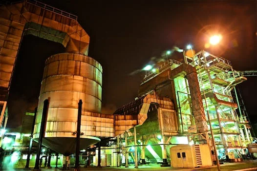
For equipment selection, the Flue Gas Desulfurization (FGD) Scrubber System page provides the process context for matching absorber arrangement, circulation, mist elimination, and wastewater interfaces to the stated gas and pollutant parameters.
Keep the existing general request path available for site navigation: technical request form. For this article’s tracked next step, send the flow rate, inlet and outlet SO₂, reagent, slurry solids, operating pH, pressure-drop trend, and suspected failure mode through the FGD troubleshooting inquiry.
Frequently Asked Questions
What are the most common causes of scaling in FGD systems?
The most common causes are high slurry temperatures, excessive calcium or dissolved solids, unstable pH, insufficient blowdown, poor reagent distribution, and mist carryover. High slurry temperatures, often exceeding 140°F (60°C), accelerate salt precipitation on nozzles, atomizer wheels, absorber internals, and mist eliminators. Operators should compare solids and pH trends with pressure drop before choosing cleaning or chemistry changes.
How can I prevent premature wear in FGD slurry pumps?
Prevent premature wear by matching the pump to particle size, solids concentration, abrasiveness, pH, and the required flow curve. Inspect suction conditions, impeller clearance, liners, seals, vibration, and motor load before increasing speed. Hard metal alloys or specialized rubber linings may suit different wear zones, but neither material choice corrects cavitation caused by inadequate suction head or an off-curve duty point.
What is the typical efficiency range for wet FGD systems in removing SO₂?
Well-designed and properly operated wet FGD systems can achieve SO₂ removal efficiencies of 90% to over 99%, depending on absorber design, operating parameters, inlet sulfur loading, reagent quality, and the required outlet limit. Treat the range as a design and operating context, not a guarantee. Confirm performance with calibrated emissions data and a representative load period.
When should I consider upgrading materials in my FGD system components?
Consider a material upgrade when wear, corrosion, cracking, or repeated scaling continues after flow, pH, solids, washing, and maintenance controls are corrected. Pump casings, impellers, piping, absorber internals, and mist eliminator supports experience different mechanisms. Review inspection records, chemistry, particle data, temperature, and failure location before selecting a hard metal alloy, rubber lining, plastic, or corrosion-resistant coating.
What is the role of pH in flue gas desulfurization?
pH controls the balance between SO₂ absorption, reagent utilization, calcium-sulfite precipitation, gypsum formation, and corrosion risk. The practical operating range described here is typically 5.0 to 6.0, while the U.S. EPA inspection manual reports 5.5 to 6.0 for fresh limestone slurry entering the absorber. The correct target remains the validated design range for the reagent and absorber.