Why Separator Coating Wastewater Is Its Own Treatment Problem
Separator coating wastewater is not a subset of electrode-coating wastewater; it has its own contaminant fingerprint, and treating it like a generic battery effluent produces undersized clarifiers, fouled membranes, and failed discharge tests. The stream comes from a narrow set of unit operations: ceramic slurry deposition (Al₂O₃ or boehmite AlOOH, particle size 0.3–3 μm) and polymer binder coating (waterborne PVDF emulsion or PVDF/acrylic hybrid), both applied to polyethylene or polypropylene film via microgravure or slot-die. Per Arkema's Kynar® technical literature, emulsion-grade PVDF is the preferred binder for waterborne separator coating because it redisperses cleanly and avoids the NMP carrier that still dominates cathode-coating lines.
Typical influent sits at COD 500–3,000 mg/L and TSS 200–1,500 mg/L, with pH 6–9, low nitrogen (TN typically <30 mg/L), and phosphorus driven almost entirely by ceramic slurry dispersants rather than biological activity. The BOD₅/COD ratio is routinely below 0.2, which is the first hard signal that a biological train is the wrong primary tool. NMP carryover is possible but secondary: waterborne PVDF emulsion lines (now the dominant route for new separator capacity) carry no NMP, but hybrid lines and some Chinese legacy lines still register 10–200 mg/L residual NMP that needs monitoring at the equalization tank.
Flow is also unstable. A single coating line produces batch discharge from coating bath dumps, a counterflow DI rinse cascade, and occasional cleaning-in-place (CIP) surges that spike pH to 11–12 and load surfactants at 50–200 mg/L. The combined diurnal swing runs 3–5x average flow, which is why equalization is non-negotiable and why a downstream DAF or membrane system will fail within weeks if the surge tank is skipped.
Influent Characterization: The Parameters That Drive Equipment Sizing
The following parameter set must be provided to vendors before requesting a quote to avoid sizing errors during commissioning.
| Parameter | Typical range (per coating line) | Driver / source |
|---|---|---|
| Flow | 5–50 m³/day | Line speed, rinse cascade ratio, CIP frequency |
| COD | 500–3,000 mg/L | PVDF emulsion stabilizers, surfactant residue |
| BOD₅ | 50–400 mg/L | Surfactants, residual organics (low BOD/COD ratio <0.2) |
| TSS | 200–1,500 mg/L | Al₂O₃/boehmite + PVDF fines |
| TDS | 200–1,500 mg/L | Salts from rinse water, dispersant carriers |
| pH | 6–9 (12+ during CIP) | Coating bath chemistry, alkaline cleaners |
| Temperature | 30–50 °C | Hot DI rinse stages, post-coating dryers |
| Total phosphorus | 5–30 mg/L | Ceramic slurry dispersants (polyacrylate-based) |
| Oil & grease | <20 mg/L (routine), up to 100 mg/L (CIP) | Defoamers, lubricant carryover |
| Particle size distribution | 0.1–5 μm (colloidal) plus 10–50 μm agglomerates | Ceramic slurry, PVDF emulsion droplets |
| F⁻ | <5 mg/L (unless co-mingled with etching) | Adjacent process only |
Two streams within this envelope drive most engineering challenges. PVDF emulsion coatings contribute 50–200 mg/L of non-settleable solids post-rinse—fine particles near neutral buoyancy that defeat a conventional clarifier and demand a properly sized industrial DAF unit for PVDF and ceramic solids removal. Ceramic-coated separators, by contrast, add 200–800 mg/L of inorganic TSS with a specific gravity of 3.9 g/cm³ for Al₂O₃; it settles readily, but the resulting sludge is hard and abrasive, wearing pump impellers and valve seats within a single service interval if not handled with hardened alloys. Surfactant loadings of 10–50 mg/L from emulsion stabilizers foam aggressively in any downstream biological stage, which is one of the main reasons MBR is usually cut from the train for this stream.
The Standard Treatment Train for Coating-Line Wastewater
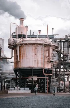
A four-stage physical-chemical train is the current industry standard for operating separator plants in China, Korea, and the EU to meet GB 30485-2013 and EU BAT-AEL discharge envelopes.
| Stage | Equipment | Key spec | Removal / role |
|---|---|---|---|
| 1. Screening & equalization | Rotary bar screen + equalization tank | 3–5 mm openings; 8–24 hr HRT | Catches film scraps; buffers 3–5x diurnal swing; pH trim to 7–8 with NaOH/HCl |
| 2. Coagulation + DAF | PAC + anionic PAM dosing; DAF | PAC 30–80 mg/L; PAM 0.5–2 mg/L; bubble size 5–80 μm; surface loading 5–20 m³/m²/hr | 85–95% TSS, 40–60% COD, removes PVDF fines and ceramic slurry |
| 3. Multimedia filtration | Anthracite-sand-garnet pressure filter | Filtration velocity 5–15 m/hr; backwash every 8–24 hr | Polishes DAF effluent to TSS <10 mg/L; protects UF/RO |
| 4. UF + RO | UF (PVDF hollow fiber) + brackish-water RO | UF pore 0.1–0.2 μm, flux 40–80 LMH; RO recovery 70–85% | UF removes colloidal residuals; RO permeate TDS <50 mg/L for DI feed or bath make-up; concentrate 15–30% to crystallizer |
Equalization comes first because nothing downstream tolerates a pH or surfactant spike. The 8–24 hr hydraulic retention time also gives the operators a place to dose antifoam before the stream hits the DAF. A rotary bar screen with 3–5 mm openings is cheap insurance against film scraps and packaging debris from coating-head changeovers, which will jam a DAF recycle pump in minutes.
Coagulation-flocculation followed by DAF is the workhorse. Polyaluminum chloride (PAC) at 30–80 mg/L plus anionic polyacrylamide (PAM) at 0.5–2 mg/L is the most common dosing envelope; cationic PAM works on some feeds but tends to overdose on PVDF emulsions. The DAF microbubble population (5–80 μm) is critical—too coarse and the PVDF fines won't attach; too fine and the bubble population collapses. An industrial DAF unit for PVDF and ceramic solids removal running at 5–20 m³/m²/hr surface loading typically removes 85–95% of TSS and 40–60% of COD in a single pass.
Multimedia filtration with an anthracite-sand-garnet multimedia filter polishing DAF effluent down to <10 mg/L TSS protects the UF and RO from premature fouling. Skipping this stage is the single most common cause of membrane replacement at 12–18 months instead of 5+ years. For sludge from the DAF float and clarifier underflow, a filter press for DAF float and ceramic sludge dewatering targeting 35–45% cake dryness is the standard—wetter cake means higher disposal tonnage, and the abrasive Al₂O₃ content will punish a belt press more than a plate-and-frame.
UF and RO for water reuse and discharge compliance close the train. UF at 0.1–0.2 μm and 40–80 LMH flux handles the colloidal residuals the multimedia filter misses; RO at 70–85% recovery produces permeate with TDS <50 mg/L suitable for DI system feed or direct bath make-up. The 15–30% concentrate is the operational headache—for a 30 m³/day line, that's 5–9 m³/day of high-TDS reject that needs either a crystallizer, an evaporator, or (where permitted) sewer discharge after polishing. MBR is rarely included because the BOD₅/COD ratio below 0.2 makes biological treatment inefficient, and ceramic fines abrade MBR membranes within one or two cleaning cycles. Where biological polishing is unavoidable, a sidestream Fenton or ozone stage is usually substituted for MBR.
Equipment Selection by Flow Rate: A Decision Matrix
The matrix below matches flow scale to equipment configuration based on 2026 industrial reference points (HydropureWater field data, 2026), excluding civil works, instrumentation, and installation.
| Line scale | Flow (m³/day) | Configuration | Key equipment | CAPEX (USD, 2026) |
|---|---|---|---|---|
| Small (R&D, pilot, single-line) | 5–15 | Skid-mounted coagulation-DAF + cartridge filter + single-pass RO | Compact DAF (DAF-1 to DAF-3), 2–4 m³/hr RO | 80,000–180,000 |
| Mid-scale (production coating line) | 15–50 | Dedicated equalization + DAF + multimedia + UF + two-stage RO | DAF-5 to DAF-20, MMF, UF skid, RO 5–10 m³/hr | 250,000–650,000 |
| Large integrated plant | 50–200 | Lamella pre-thickener + DAF + multimedia + UF + RO with energy recovery | Lamella clarifier, DAF-30+, full UF/RO train with ERD | 1,000,000–3,500,000 |
If water reuse >60% is a project requirement—typical in China GB 30485-2013 enforcement zones, Korean industrial complexes with intake restrictions, and EU BAT-aligned plants—RO is mandatory. If the project is discharge-only, the RO stage can be replaced by lower-cost ion exchange or advanced oxidation (Fenton, ozone) targeting the dissolved COD fraction that survives DAF and multimedia. For lines >15 m³/day, a lamella clarifier pre-thickening stage ahead of the DAF reduces DAF loading and improves float solids content by 30–50%, which directly improves downstream filter-press performance. A rotary bar screen at the head of the train is recommended for any plant handling biaxially oriented polypropylene (BOPP) film scraps from coating-head changeovers.
2026 Discharge Compliance and Water Reuse Targets
Regulatory targets in the three main jurisdictions vary significantly for separator coating wastewater.
| Jurisdiction | Standard | COD (mg/L) | SS (mg/L) | NH₃-N (
ReferencesGet a Free Quote — Tell Us About Your Project
Contact Us
|
|---|