Why Aeration Design Is the Largest Economic Lever in a Municipal Plant
Municipal aeration design converts influent BOD and ammonia into field oxygen demand, then into SOTR with alpha, depth, and elevation corrections. Fine-bubble grids at 4-7 m sidewater depth usually give the highest clean-water SOTE for new activated-sludge basins. Design airflow follows design SOTR divided by clean-water transfer efficiency, with a 1.2-1.5 safety factor for peaks and fouling.
Aeration often dominates plant power use. Earlier industry summaries often cited 45-75% of total plant energy for aeration. According to EPA 832-R-10-005 (2010), the fraction ranges from 25 to as much as 60 percent of total plant energy use (citing WEF 2009). For a 10,000 m³/d facility at $0.10/kWh, that still means roughly 2.5-4 million kWh/year and $250,000-$400,000 in annual electricity for a single process. A 10-percentage-point gain in standard oxygen transfer efficiency (SOTE) cuts blower power across a 20-30 year asset life. Undersizing the basin remains a common root of effluent violations; Clean Water Act enforcement actions have reached $4.1 million in documented cases.
Municipal Aeration Design Calculation Chain: From Influent BOD to SOTR
Diffused aeration design for a municipal activated sludge process follows a fixed four-step chain. First calculate field oxygen demand, then convert to standard oxygen requirement (SOR) with water-quality factors. Next convert to standard oxygen transfer rate (SOTR) with atmospheric and depth adjustments, then apply a safety factor. Step 1 answers how much oxygen biology needs. Step 2 answers what clean-water testing understates for this mixed liquor. Step 3 answers what field submergence and elevation change. Step 4 answers how much margin remains for peak load and fouling.
Step 1 — Field oxygen demand (AOR, actual oxygen requirement): Carbonaceous demand is typically 1.2-1.5 kg O₂/kg BOD removed for conventional activated sludge; nitrification adds 4.6 kg O₂/kg NH₃-N oxidized. Designers commonly include a small credit for denitrification (2.9 kg O₂/kg NO₃-N reduced) if anoxic zones are present.
Step 2 — Convert AOR to SOR (standard oxygen requirement at 20°C, zero dissolved oxygen, 1 atm). Use SOR = AOR / (α × F) × [β × Csw,T - CL] / [Csw,20] × 1 / θ(T-20). Here α is typically 0.5-0.9 for fine-bubble diffusers in mixed liquor, β is 0.95-1.0, and θ ≈ 1.024. T is water temperature in °C, CL is the DO setpoint (commonly 2.0 mg/L), and Csw is clean-water saturation concentration.
Step 3 — Convert SOR to SOTR for site conditions. Atmospheric pressure drops ~1% per 82 m above sea level, and each meter of submergence adds roughly 1% effective saturation. At 5 m submergence the depth correction can be 15-25%.
Step 4 — Apply a safety factor of 1.2-1.5 to cover peak diurnal loading, diffuser fouling between cleaning cycles, and biological model uncertainty. Final air flow is then derived from SOTR divided by the diffuser's clean-water oxygen transfer efficiency.
| Step | Output | Key Correction Factors | Typical Range / Value |
|---|---|---|---|
| 1. Field demand | AOR (kg O₂/h) | BOD removal, nitrification stoichiometry | 1.2-1.5 kg O₂/kg BOD; 4.6 kg O₂/kg NH₃-N |
| 2. AOR → SOR | SOR (kg O₂/h) | α, β, temperature, DO setpoint | α = 0.5-0.9; β = 0.95-1.0; θ = 1.024 |
| 3. SOR → SOTR | SOTR (kg O₂/h) | Site elevation, diffuser submergence | +1%/m depth; -1%/82 m elevation |
| 4. Design margin | Design SOTR | Peak load, fouling, redundancy | × 1.2-1.5 |
Diffused vs Mechanical vs Jet: Matching Configuration to Tank Geometry and Load
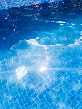
Equipment selection for municipal aeration basins is depth-driven first, then load-driven. Fine-bubble membrane diffusers dominate modern activated-sludge designs at 4-7 m sidewater depth. They deliver the highest clean-water SOTE per unit air at the lowest specific power. Coarse-bubble diffusers are reserved for grit chambers, equalization basins, and high-solids applications where fouling tolerance matters more than efficiency. Mechanical surface aerators remain common in deep-shaft and oxidation-ditch configurations where footprint and draft-tube geometry favor surface oxygen entrainment. Jet aeration combines liquid recirculation with compressed-air injection through a nozzle. It eliminates in-basin moving parts and can cut energy costs up to 40% in deep-tank retrofits (per Mixing.com). That makes jet aeration strong for existing deep tanks where diffused retrofits would be impractical. For designers comparing options, the WEF WSEC-2017 Table 1 SOTR ranges provide the cleanest head-to-head efficiency basis.
| Configuration | SOTR Range (lb O₂/hp·h) | Typical Municipal Application |
|---|---|---|
| Fine-bubble diffuser | 2.0-3.3 | Conventional activated sludge, 4-7 m depth |
| Medium-bubble diffuser | 1.6-2.6 | Intermediate duty, mixed liquor |
| Coarse-bubble diffuser | 1.0-2.0 | Grit chambers, equalization, high-solids |
| Jet aeration | 2.0-4.0 | Deep tanks, retrofit, no in-basin moving parts |
| U-tube | 2.1-4.0 | Very deep shafts (>7 m) |
| Surface low-speed | 2.5-3.5 | Oxidation ditches, deep-shaft |
| Surface high-speed | 1.8-2.3 | Lagoons, equalization |
Footprint rules of thumb still guide layout: mechanical surface aerators require 0.5-1.0 W/m² of basin floor. Diffused systems target diffuser density of 15-25% floor coverage for fine-bubble designs. Engineers evaluating MBR-coupled plants often pair aeration with an integrated MBR membrane bioreactor system. That pairing imposes a tighter dissolved oxygen setpoint (typically 1.5-2.5 mg/L in the MBR tank) and a higher sustained OTR. Both shifts favor fine-bubble diffusion with high-density grids. Flat-sheet modules such as DF series flat sheet membrane modules further fix the required air scour and process-air split in those trains.
Which aeration tech fits capacity expansion?
Capacity-expansion aeration choices follow existing tank depth and permit oxygen demand before brand preference. Plants adding load at 4-6 m sidewater depth usually extend fine-bubble grids and upsize turbo or multi-stage blowers rather than converting to surface aerators. Deep tanks above 7 m, or basins that cannot accept floor grids, often justify jet aeration or U-tube options instead of a full basin rebuild. Match SOTR capacity to the new peak AOR with the same alpha and safety-factor rules used for greenfield design.
Worked Example: Designing Aeration for a 10,000 m³/d Municipal Plant
A 10,000 m³/d municipal plant example uses influent BOD = 200 mg/L and an effluent BOD target = 20 mg/L. Sidewater depth is 5 m, MLSS is 3,000 mg/L, water temperature is 15°C, site elevation is 100 m, and target DO is 2.0 mg/L.
Step 1 — BOD removed: 10,000 × (200-20)/1,000 = 1,800 kg BOD/d. At a 1.2-1.5 factor, oxygen demand = 2,160-2,700 kg O₂/d, or 90-113 kg O₂/h.
Step 2 — AOR to SOR uses α = 0.65, β = 0.98, θ = 1.024, T = 15°C, CL = 2.0 mg/L, and Csw,20 ≈ 9.1 mg/L. The correction term is approximately 0.65 × 0.98 × 9.092 × 1.024(-5) ÷ (9.1 - 2.0) ≈ 0.49. SOR ≈ 184-230 kg O₂/h.
Step 3 — SOR to SOTR: 5 m submergence adds ~15%, and 100 m elevation subtracts ~1%, net correction ×1.14. SOTR ≈ 210-262 kg O₂/h. Apply a 1.3 safety factor: design SOTR ≈ 273-341 kg O₂/h.
Step 4 — Hardware selection starts from transfer efficiency. Fine-bubble membrane diffusers at 9 mm typically deliver 2.5 lb O₂/hp·h (~1.5 kg O₂/kWh) at 5 m. Required design airflow = SOTR / (clean-water SOTE × 0.21 × 1.43 kg O₂/Nm³ air) ≈ 1,800-2,300 Nm³/h. At 20-25 diffusers per 100 m² and 5 m grid spacing, a 10,000 m³/d plant typically needs 300-500 fine-bubble diffusers across two parallel trains. Blower power at 50 kPa discharge is about 30-40 kW per train. Two duty blowers plus one standby yield installed capacity around 100-120 kW. Annual energy = 100 kW × 8,000 h = 800,000 kWh/year, or about $80,000/year at $0.10/kWh.
| Parameter | Fine-Bubble Case | Coarse-Bubble Case | Delta |
|---|---|---|---|
| Design SOTR (kg O₂/h) | ~310 | ~310 | — |
| SOTR (lb O₂/hp·h) | 2.5-3.3 | 1.0-2.0 | Fine-bubble ~1.6× more efficient |
| Required blower kW | ~100 | ~180 | +80% power |
| Annual energy (kWh) | 800,000 | 1,440,000 | +640,000 kWh |
| Annual cost (@ $0.10/kWh) | $80,000 | $144,000 | +$64,000/year |
The coarse-bubble alternative imposes an energy penalty of roughly $64,000/year — a $1.3M cumulative penalty over a 20-year design life at flat electricity cost, before escalation. This delta is why the WEF table values directly drive specification, not just configuration choice.
Blower Selection, Piping, and Aeration Grid Layout
Blower type for municipal aeration follows airflow and turndown needs. Positive-displacement (PD) blowers suit variable air demand below 2,000 Nm³/h, common in smaller plants or side-stream re-aeration. Multi-stage centrifugal blowers cover mid-size plants from 2,000-15,000 Nm³/h with reasonable turndown. Turbo blowers are direct-drive high-speed units with integrated variable-frequency drives. They deliver 50-70% energy savings on constant or slowly varying loads and now dominate new municipal installations above 3,000 Nm³/h. Air header design keeps main-header velocity at 9-15 m/s and lateral velocity at 4-6 m/s to minimize pressure loss. Every 1 kPa of unnecessary pressure loss adds roughly 1% to blower power. Drop legs land on 0.6-1.0 m centers with a dual-grid arrangement that allows step-feed and tapered aeration. That layout matches oxygen supply to declining demand along the basin length. Diffuser fouling degrades SOTE 20-30% over five years between cleaning cycles. Design must therefore treat clean-water performance as a starting point, not the steady-state operating point. Pretreatment screening with a rotary mechanical bar screen at 3-6 mm opening extends diffuser life by removing fibrous material that accelerates biological fouling.
How should plants procure aeration equipment?
Procurement packages for aeration equipment should freeze design SOTR, turndown ratio, and diffuser cleaning access before bid documents issue. Specify clean-water SOTE or SAE at stated submergence, alpha assumptions at design MLSS, and blower wire-to-air efficiency across the expected airflow band. Require factory or field oxygen-transfer verification, spare diffuser inventory, and documented header pressure drop at peak airflow. Separate process-air and membrane-scour air duties when MBR trains are included, and keep O&M manuals and cleaning intervals in the contract, not only in vendor brochures.
Compliance Floors and Design Verification: Meeting 40 CFR 133
Secondary treatment under 40 CFR 133.102 sets the aeration design floor for municipal plants. The 30-day average BOD₅ shall not exceed 30 mg/L, SS shall not exceed 30 mg/L, and effluent pH shall stay within 6.0 to 9.0. The rule also requires at least 85 percent 30-day average BOD₅ and SS removal. According to the current eCFR text of 40 CFR 133.102, NPDES authorities may substitute CBOD₅ limits of 25 mg/L (30-day) and 40 mg/L (7-day) in lieu of BOD₅. Many state and POTW permits impose tighter limits. BOD ≤20 mg/L is common, and seasonal ammonia limits of NH₃-N ≤5 mg/L in summer (≤10 mg/L in winter) are now standard across most U.S. states. Both tighter BOD and ammonia limits raise required SOR. The dissolved oxygen setpoint must hold 2.0 mg/L minimum in the aeration tank to maintain floc structure, prevent filamentous bulking, and support complete nitrification. Designers should verify local authority effluent limits before freezing hardware, because the design is judged against the most stringent applicable number. Broader municipal sewage treatment plant engineering specs vary materially by state, so verifying local limits is non-optional.
Selection Checklist Before Freezing Hardware
Municipal plant teams should lock these items before ordering blowers or diffuser grids:
- Peak and average AOR from BOD removal plus nitrification stoichiometry at design temperature.
- Alpha, beta, DO setpoint, and site elevation/submergence corrections used to compute SOTR.
- Diffuser type matched to sidewater depth and solids duty (fine-bubble, coarse-bubble, or jet).
- Blower type and turndown for the design airflow band, with N+1 redundancy stated.
- Header velocity limits (9-15 m/s main, 4-6 m/s lateral) and allowable pressure loss.
- Fouling allowance and cleaning interval reflected in the safety factor, not ignored.
- Most stringent local BOD, TSS/SS, ammonia, and DO permit numbers confirmed in writing.
Who this is for: process engineers, EPC designers, and utility procurement staff sizing municipal activated-sludge aeration. Who should look elsewhere: teams specifying only lift-station pumps or non-aerated lagoon systems. Next step: compile influent loads, basin depth, and permit limits, then request a free quote with flow rate and pollutant parameters if equipment options need vendor sizing support.
Frequently Asked Questions

What alpha factor should I use for fine-bubble diffusers in mixed liquor?
Typical α values are 0.5-0.9 for fine-bubble diffusers in mixed liquor. Use 0.6-0.7 for conventional activated sludge at MLSS 2,500-3,500 mg/L. Run a side-by-side clean-water and field oxygen-transfer test during commissioning. Textbook midpoints alone are not a substitute for site verification at design solids and temperature.
How do I convert AOR to SOTR for a site at 500 m elevation with 6 m submergence?
Subtract roughly 6% for elevation (500/82 × 1% per 82 m) and add roughly 18% for 6 m submergence, then apply the alpha, beta, and temperature corrections from the calculation chain. At α = 0.65, β = 0.98, and T = 15°C, the net field-to-SOTR multiplier typically lands near 2.0-2.2× the AOR under those site conditions.
What is the typical SOTE for a 9-inch membrane fine-bubble diffuser at 5 m depth?
Clean-water SOTE for a quality 9-inch membrane fine-bubble diffuser at 5 m submergence typically lands between 38-45% per the WEF WSEC-2017 ranges. Expect 28-35% in mixed liquor after alpha correction at design MLSS. Use the field value, not clean-water SOTE alone, when sizing steady-state blower power.
How many diffusers does a 10,000 m³/d plant typically need?
For a 10,000 m³/d plant at 200 mg/L influent BOD, 5 m depth, and α = 0.65, expect 300-500 fine-bubble diffusers across two parallel trains with dual grids. Total design airflow lands around 1,800-2,300 Nm³/h. Final counts still depend on diffuser density, orifice size, and the applied safety factor.
When is jet aeration more cost-effective than fine-bubble diffusion?
Jet aeration is generally favored in retrofits of existing deep tanks (>7 m) where diffused systems would require basin modification, and where eliminating in-basin moving parts is a maintenance priority. For new municipal activated-sludge basins at 4-6 m sidewater depth, fine-bubble diffusion typically wins on energy per kg O₂ transferred over a 20-year evaluation period.