AOP semiconductor wastewater CAPEX ranges from $250K for a small-scale MBR train to $417M for a full zero-liquid-discharge plant, with OPEX of $0.40–$6.00 per m³ depending on the MBR, RO, AOP, and ZLD configuration a fab selects.
Why Semiconductor Wastewater Demands Fab-Specific Engineering
Semiconductor fabs discharge hydrofluoric acid (HF) above 100 mg/L and tetramethylammonium hydroxide (TMAH) above 500 mg/L, both toxic to the activated-sludge biomass used in municipal plants. Federal rule 40 CFR Part 469 Subpart A covers semiconductor manufacturing discharges, while EU directives and China's GB 31573-2015 cap COD, fluoride, and ammonia at low mg/L levels.
Wafer fabrication chemistry explains why standard industrial systems struggle. Photoresist stripping, etching, and chemical mechanical planarization (CMP) produce an effluent that is simultaneously toxic to biological life and corrosive to standard infrastructure, and the blend shifts with every process change on the line. Most fabs we size for split these streams at source rather than fight one combined stream.
Conventional biological treatment often fails in fab service. HF concentrations above 5 mg/L significantly inhibit microbial growth, leading to biomass death and system collapse, while TMAH is highly toxic to the activated sludge in municipal-grade plants. Under EPA 2023 guidelines, TMAH requires specialized nitrification/denitrification or advanced oxidation before discharge is environmentally safe.
Regulatory pressure keeps tightening. The EU Industrial Emissions Directive sets HF limits at ≤1 mg/L, and supplier datasheets have long quoted SEMI S23 with TMAH below 1 mg/L for safe discharge. That framing deserves a correction. SEMI S23 is a resource-efficiency guide for semiconductor manufacturing equipment — it covers conservation of energy, utilities, and materials, not effluent limits — so sub-1 mg/L TMAH targets come from each fab's discharge permit, not from SEMI.
Circular water targets add a second engineering driver. Fabs increasingly treat effluent for reuse as cooling tower makeup or as feedwater for ultrapure water (UPW) systems, which pairs high-recovery filtration with robust chemical pre-treatment. The train must absorb fluctuating influent loads while holding a steady output of reclaimed water, and end-to-end removal targets of 99.9% on key toxicants are now standard in fab specifications.
Technology Comparison: MBR vs. RO vs. AOP vs. ZLD
Technology selection follows waste-stream chemistry: TMAH, organics, and TSS point to MBR; dissolved ions point to RO; refractory COD points to AOP; and brine volume points to ZLD. A semiconductor wastewater treatment supplier worth shortlisting matches the train to the stream and to the discharge or reuse goal. The matrix below compares the four main options.
| Technology | Contaminants Treated | Removal Efficiency | Footprint (m²/100 GPM) | Scalability (GPM range) |
|---|---|---|---|---|
| MBR (Membrane Bioreactor) | TMAH, Organics, TSS | 99.9% TMAH, 95% COD | 5–10 m² | 50–2,000 GPM |
| RO (Reverse Osmosis) | TDS, Ions, Organics | 95% TDS, 90% COD | 3–8 m² | 100–1,500 GPM |
| AOP (Advanced Oxidation) | VOCs, Refractory COD | 92–97% COD | 2–5 m² | 50–1,000 GPM |
| ZLD (Zero Liquid Discharge) | All Contaminants | 99% Water Recovery | 20–50 m² | 500–5,000+ GPM |
MBR is the workhorse for organic-rich etching streams — our MBR engineering specs for etching wastewater detail reactor design at these fluxes — and it is often paired with RO for high-purity reuse. RO handles wafer cleaning streams well but fouls quickly if HF is not neutralized in pre-treatment. AOP is reserved for the most recalcitrant organic compounds that biology cannot break down, while ZLD delivers the highest water recovery at the highest energy intensity and capital cost.
AOP Semiconductor Wastewater CAPEX Benchmarks and 2026 Engineering Specs
AOP semiconductor wastewater CAPEX cannot be quoted without four spec anchors: design membrane flux of 15–25 LMH, RO recovery of 75–95%, AOP COD removal of 92–97%, and UV dose of 500–1,000 mJ/cm². A supplier who quotes a lump sum before fixing those numbers is guessing at the load case. The parameter set below reflects current industry benchmarks for reliable performance.
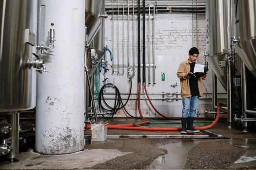
Modern MBR systems for semiconductor wastewater use PVDF (polyvinylidene fluoride) hollow-fiber or flat-sheet membranes with a nominal pore size of 0.1 μm. Design flux runs at 15–25 LMH with MLSS held at 8,000–12,000 mg/L, and energy consumption typically lands between 0.6 and 1.2 kWh/m³ depending on the aeration duty that TMAH degradation demands. Units we commission at the lower end of that energy band are the ones with stable, segregated TMAH feed.
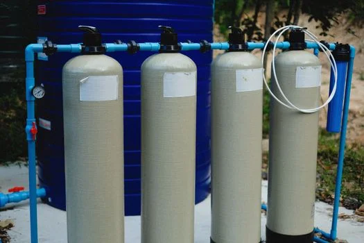
Recovery rate is the critical KPI for RO systems for rinse and etching wastewater. High-efficiency skids reach 95% recovery on dilute rinse wastewater and roughly 75% on complex etching streams, with membrane life of 3–5 years supported by automated CIP (Clean-In-Place) cycles. Detailed RO engineering specs for wafer cleaning wastewater show why anti-fouling spacers in the membrane modules matter at these recoveries.
Advanced oxidation and evaporation close the loop at the top end. AOP trains need a UV dose of 500–1,000 mJ/cm² with H₂O₂ dosing of 10–50 mg/L to reach 97% COD removal. For fabs in water-stressed regions, ZLD systems using MVR (Mechanical Vapor Recompression) or MEE (Multi-Effect Evaporation) recover 90–95% of the brine stream, though energy demand climbs to 20–50 kWh/m³. That last figure is why ZLD is a siting decision as much as a treatment one.
Pre-treatment remains the stage that decides membrane survival. Precise pH adjustment (HF streams at 7–9, TMAH streams at 6–8) and metals precipitation keep copper (Cu) and nickel (Ni) below 0.1 mg/L before water reaches sensitive membrane stages. For disinfection of reuse water, ClO₂ generators for UPW disinfection are often integrated to prevent biofouling in storage tanks.
Semiconductor Wastewater Treatment CAPEX Breakdown by Scale
Semiconductor wastewater treatment CAPEX breaks down along capacity bands, materials of construction, and the automation level a fab specifies. The figures below pair initial CAPEX with the OPEX lines that dominate a 10-year ownership view: membrane replacement and chemical dosing.
| System Type | Capacity (GPM) | Estimated CAPEX | Estimated OPEX ($/m³) |
|---|---|---|---|
| Small-Scale MBR | 50–200 | $250K – $1.2M | $0.60 – $1.30 |
| Large-Scale MBR | 500–2,000 | $1.5M – $5M | $0.40 – $0.90 |
| Standard RO Unit | 100–1,500 | $500K – $10M | $0.50 – $1.50 |
| Full ZLD Plant | 500–5,000 | $10M – $417M | $2.50 – $6.00 |
CAPEX moves most with materials and automation. High-grade stainless steel versus specialized plastics for HF resistance can swing the equipment line on its own, while OPEX is driven by energy in RO and ZLD trains and by chemicals for pH neutralization and AOP dosing. For a plant-level view of the flowsheet, our companion article Semiconductor Wastewater Treatment Plant: 2026 Engineering Specs, Zero Liquid Discharge Design & Cost Benchmarks works through ZLD layout stage by stage.
- Water reuse savings: reclaiming wastewater for UPW production saves between $1.50 and $5.00 per cubic meter, depending on local municipal water rates.
- Regulatory avoidance: fines for EPA or EU discharge violations range from $10,000 to $100,000 per incident, before counting the cost of a potential fab shutdown.
- Sustainability incentives: many regions offer tax credits or subsidies, such as EU Green Deal credits, for fabs that implement high-recovery or zero-discharge technologies.
One documented case frames the upside. A $417M ZLD facility cut its potable water purchase by 30%, reaching a 5-year payback through water cost savings and eliminated discharge fees alone. Numbers at that scale are site-specific, but the direction is consistent: water-stressed regions pay back ZLD fastest.
AOP Cost Model for Fab Wastewater 2026: Lines That Decide the Bid
An AOP cost model for fab wastewater in 2026 is built from UV lamp energy at a 500–1,000 mJ/cm² dose, H₂O₂ dosing of 10–50 mg/L, and the replacement intervals of lamps, sleeves, and quench chemicals. Contracted COD removal usually sits in the 92–97% band, and each extra point of removal costs more oxidant and UV energy than the one before it.
Chemical consumption is the line item buyers most often underbudget. Ask every bidder for exact H₂O₂ dosing per m³ at your influent COD, plus pH-correction reagents and the quench agent that protects downstream membranes from residual oxidant. Energy for the UV banks adds a steady kilowatt load per train, so the OPEX quote should separate it from chemical spend.
Cross-industry benchmarks travel badly into fab service, so calibrate them. Our aop wastewater capex guide covers advanced-oxidation economics for organic industrial streams and makes a useful sanity check on supplier quotes. Semiconductor influent — fluoride, TMAH, CMP abrasives — carries pre-treatment costs those numbers exclude. Most AOP trains we size for CMP-heavy streams end up paired with biological pre-treatment rather than standing alone.
Regulatory Requirements: Compliance Strategies for Global Fabs
Global semiconductor wastewater compliance rests on three rulebooks: 40 CFR Part 469 in the United States, the EU Industrial Emissions Directive, and China's GB 31573-2015. Each sets different limits for fluoride, copper, and organic solvents, and a supplier must map the fab's discharge point to the right one before quoting performance.
US rules date to 1983 but still govern the permit. According to the US EPA, the Electrical and Electronic Components Effluent Guidelines and Standards (40 CFR Part 469) were promulgated in 1983, with Subpart A covering the Semiconductor Subcategory (US EPA). EPA's detailed study (EPA-821-R-22-005, November 2022) concluded that its review of monitoring data does not demonstrate a need to revise the existing regulation at this time, and the agency intends to continue to monitor PFAS discharges from the category.
Supplier datasheets citing COD ≤125 mg/L and TSS ≤30 mg/L under Part 469 are typically quoting site-specific NPDES permit values rather than the federal floor. Fluoride stays strictest in sensitive groundwater areas, often capped at 1 mg/L. Both numbers belong in the contract's compliance schedule, with the permit cited as the source.
The EU framework tightened in 2024. The Industrial Emissions Directive (2010/75/EU) emphasizes Best Available Techniques (BAT), which often push fabs toward AOP for VOC removal and MBR for nitrogen management, while HF limits of ≤1 mg/L frame pre-treatment design. According to the European Commission, the revised directive (Directive (EU) 2024/1785, the IED 2.0) entered into force on 4 August 2024. BAT conclusions now form the basis for permit conditions, harmonised on-site inspections run at least every one to three years, and the worst infringements draw strengthened fines of at least 3% of annual EU turnover.
China's GB 31573-2015 remains among the strictest electronic-industry standards worldwide, requiring COD as low as 60 mg/L and ammonia nitrogen (NH₃-N) ≤8 mg/L. For fabs facing those numbers on constrained sites, zero liquid discharge is often the only route to full, year-round compliance. SEMI S23 rounds out the picture as an industry benchmark for EHS and resource-efficiency reporting, with TMAH removal efficiency tracked to protect local aquatic ecosystems.
Supplier Selection Framework: 10 Questions to Ask Before Signing
Supplier evaluation comes down to documented performance at your chemistry, not datasheet adjectives. Engineering and procurement teams should put these ten questions to every shortlisted vendor and expect numbers back.
- TMAH removal: What is the documented TMAH removal efficiency at an influent concentration of 500 mg/L? (Target: >99.9%)
- Membrane flux: What design flux (LMH) will you contract for high-HF wastewater streams, and what cleaning frequency does it imply? (Target: 10–15 LMH for high-strength waste)
- Performance commitment: Can you provide a legally binding performance commitment for EPA/EU discharge limits, with financial penalties for non-compliance?
- Pilot testing: Do you offer on-site pilot testing for 3–6 months to validate treatment of the fab's specific process chemistry?
- CAPEX/OPEX transparency: What is the total cost of ownership for a 500 GPM system over a 10-year period, including membrane replacements?
- Uptime commitment: What uptime will you contract for critical fab operations, and how are redundant components handled? (Target: 98%+)
- Remote monitoring: Does the system include 24/7 remote monitoring and predictive maintenance alerts to prevent unplanned downtime?
- Chemical consumption: What is the exact chemical dosing requirement per cubic meter — H₂O₂, pH reagents, coagulant — at the design load?
- Fluoride sludge handling: What CaF₂ sludge volume and classification should the site plan for, and is dewatering equipment inside the scope?
- Reference plants: Which fabs running comparable GPM and process chemistry can we contact directly?
Next Step: From Specs to a Costed Package
A shortlist of two or three suppliers should now collapse to one on pilot data and contracted performance numbers. Share the influent characterization — HF, TMAH, and CMP loads in mg/L — plus target discharge limits and reuse goals, then ask each vendor for a budgetary CAPEX/OPEX split in your GPM band. Our engineers can assemble that package, including a preliminary semiconductor fab wastewater treatment flowsheet; start with a detailed inquiry for semiconductor wastewater treatment and we will respond with sizing and budget numbers.
Frequently Asked Questions
What does a semiconductor fab AOP CAPEX OPEX analysis include?
A complete analysis covers the oxidation train (UV dose of 500–1,000 mJ/cm², H₂O₂ dosing of 10–50 mg/L) and its 92–97% COD-removal band, plus the polishing steps that follow. On the CAPEX side, price the skid materials, dosing systems, and interlocks against HF and fluoride duty. On the OPEX side, include lamp and sleeve replacement, quench chemicals, energy per m³, and the labor to service them at your GPM band.
What drives TMAH wastewater treatment system cost?
TMAH system cost is driven by influent concentration, the removal route, and the reuse target. At a 500 mg/L design point, a biological route — MBR at 15–25 LMH, MLSS of 8,000–12,000 mg/L, 0.6–1.2 kWh/m³ — usually costs less per m³ than advanced oxidation but needs stable loading. Removal targets above 99.9% push the design toward MBR plus AOP polishing, raising both CAPEX and chemical OPEX.
Which discharge limits apply to semiconductor fabs in 2026?
Semiconductor fabs answer to 40 CFR Part 469 Subpart A in the US, the EU Industrial Emissions Directive as revised by Directive (EU) 2024/1785, and China's GB 31573-2015. Part 469 was promulgated in 1983 (US EPA), and site NPDES permits often add COD ≤125 mg/L and TSS ≤30 mg/L. GB 31573-2015 sets COD as low as 60 mg/L and NH₃-N ≤8 mg/L.
Can fab wastewater be reused as ultrapure water feed?
Yes, most new fabs design rinse-water reclaim for reuse as cooling tower makeup and, after RO polishing at 95% recovery on dilute streams, as feed to ultrapure water trains. Reuse economics typically save $1.50–$5.00 per m³ against municipal water rates. One $417M ZLD facility cut potable purchases by 30% with a 5-year payback, so HF and TMAH pre-treatment stability is what decides whether reclaim quality holds.
How long should on-site pilot testing run before purchase?
Plan 3–6 months of on-site piloting to validate TMAH, HF, and CMP chemistry across batch and seasonal swings. That window exposes flux decline, cleaning frequency, and dosing drift that desktop sizing misses, and it produces the documented removal data your contract should reference. Vendors unwilling to pilot at your flows rarely support binding performance commitments either.