MBR etching wastewater treatment at semiconductor fabs achieves 99.9% TMAH removal and fluoride discharge below 1 mg/L when calcium precipitation and silica control run upstream; a 100 m³/h train costs $1.2M–$2.5M.
MBR Etching Wastewater Treatment for Semiconductor Fabs: Why Conventional Systems Fail
Etching wastewater carries TMAH at 500–5,000 mg/L, fluoride at 100–1,000 mg/L and colloidal silica at 50–300 mg/L. Conventional activated sludge fails on all three: TMAH above 200 mg/L inhibits nitrifiers, fluoride needs chemical precipitation, and silica fouls membranes. MBR with calcium precipitation, UF pretreatment and RO polishing closes the gap at 95% recovery.
Tetramethylammonium hydroxide (TMAH), a key component in developers and etchants, severely inhibits the nitrifying bacteria responsible for ammonia removal. TMAH concentrations exceeding 200 mg/L are known to inhibit nitrification, leading to ammonia-nitrogen (NH₄-N) exceedances in activated sludge systems (per EPA 2023 benchmarks). The hazard is not only biological. TMAH baths typically run 5–25 wt.% at 70–90 °C for anisotropic silicon etching, and the compound is acutely toxic — GHS H300+H310, fatal if swallowed or absorbed through skin (Wikipedia, Tetramethylammonium hydroxide). Permits tighten on it accordingly.
Beyond TMAH, etching wastewater contains fluoride (100–1,000 mg/L) from hydrofluoric acid (HF) processes, which is toxic to microorganisms and requires specialized chemical precipitation. Colloidal silica, typically at 50–300 mg/L, presents a significant physical challenge. Silica forms stable suspensions that are difficult to settle in clarifiers and readily co-precipitates with calcium fluoride during chemical treatment, leading to severe membrane fouling. A 2025 Saltworks XtremeUF study demonstrated that silica co-precipitation during calcium precipitation can reduce membrane flux by 30–50% without adequate pretreatment.
The consequences are severe. In 2024, a major Tier-1 semiconductor fab in East Asia faced a $2.1M regulatory fine after its conventional 3-stage activated sludge system, which lacked dedicated silica removal, discharged effluent exceeding Chinese limits for TMAH and NH₄-N. That incident is usually reported against GB 31573-2015; note that GB 31573-2015 is the discharge standard for the inorganic chemical industry. Shanghai's local semiconductor standard, effective from 2023, is stricter still. Confirm the GB number cited in your own permit before design freeze. This is where membrane bioreactors (MBR) move past traditional biological and physical separation, including in broader industrial wastewater treatment practice adapted to etching chemistry.
TMAH Removal Membrane Bioreactor Design: Key Parameters and Trade-offs
TMAH removal membrane bioreactor design centers on five numbers: MLSS, HRT, SRT, flux and scouring air. The mixed liquor suspended solids (MLSS) concentration in an MBR for etching wastewater typically ranges from 5,000–8,000 mg/L, significantly higher than the 3,000–5,000 mg/L common in municipal applications. This elevated MLSS is necessary to degrade the high COD concentrations (500–2,000 mg/L) characteristic of etching effluent, while balancing the risk of increased viscosity and fouling above 10,000 mg/L MLSS.
Hydraulic retention time (HRT) for TMAH degradation generally requires 8–12 hours, longer than the 4–6 hours for municipal wastewater. A longer HRT promotes more stable biological activity and can reduce membrane fouling by allowing more complete organic degradation and a more stable floc structure, although it necessitates a larger reactor footprint (2025 WEF study on HRT vs. flux stability). Sludge retention time (SRT) is maintained at 20–30 days to ensure the proliferation and resilience of nitrifying bacteria, which are essential for ammonia removal but sensitive to TMAH toxicity. A longer SRT also reduces sludge production, impacting disposal costs and cleaning frequency.
Aeration in the membrane tank is critical for both biological activity and membrane scouring. Coarse-bubble aeration at 0.2–0.4 m³/m²·h is typically employed for membrane scouring, providing sufficient shear to dislodge foulants. This approach can reduce energy costs by 15% compared to fine-bubble aeration, which is less effective for physical membrane cleaning (HydropureWater DF Series energy data). For submerged PVDF MBR systems for etching wastewater with 0.1 μm pore sizes, a typical membrane flux rate is 15–25 LMH (liters per square meter per hour). For influent with high silica concentrations, a conservative flux of 10–15 LMH is recommended to prevent premature fouling and extend membrane lifespan.
| Parameter | Etching Wastewater MBR (Typical Range) | Impact/Trade-off |
|---|---|---|
| MLSS | 5,000–8,000 mg/L | Higher for COD degradation, but >10,000 mg/L increases viscosity and fouling. |
| HRT | 8–12 hours | Longer for TMAH degradation and flux stability, increases footprint. |
| SRT | 20–30 days | Maintains nitrifying bacteria, reduces sludge production. |
| Membrane Flux (PVDF) | 15–25 LMH (10–15 LMH for high silica) | Lower flux for high silica reduces fouling, but increases membrane area. |
| Aeration Rate (Scouring) | 0.2–0.4 m³/m²·h (coarse bubble) | Effective foulant removal, 15% energy savings vs. fine bubble. |
Pretreatment Strategies to Prevent Membrane Fouling: Calcium Precipitation, Silica Removal, and pH Control

Calcium Precipitation for Fluoride Removal in Etching Wastewater
Calcium precipitation is highly effective for fluoride removal, achieving 95–99% efficiency when maintained at a pH of 8–9. The process typically involves dosing calcium chloride (CaCl₂) at 1.5–2.0 times the stoichiometric ratio to the fluoride concentration, forming insoluble calcium fluoride (CaF₂) precipitates (per EPA 833-B-19-001). Know the floor before promising a number: CaF₂ solubility sits at 15–16 mg/L at 18–20 °C with Ksp 3.9×10⁻¹¹ (Wikipedia, Calcium fluoride). Plain precipitation alone cannot chase <1 mg/L residuals — overdosing, co-precipitation and the downstream RO barrier do that work.
Silica Fouling Prevention in MBR Pretreatment
Silica fouling prevention in MBR pretreatment starts with holding pH at 6–7, which keeps silica in a more soluble form, or installing ultrafiltration (UF) as a dedicated silica removal step. Advanced UF systems employing 0.02 μm membranes like Saltworks XtremeUF can remove colloidal silica before the MBR stage, protecting downstream membranes from the 30–50% flux loss documented when silica co-precipitates with calcium fluoride (Saltworks XtremeUF 2025 data). On high-silica feeds, derating design flux to 10–15 LMH is the second line of defense.
Precise pH control is also essential for optimal biological treatment, with a target range of 7.5–8.5 for the MBR. Deviations outside this range inhibit microbial activity and reduce treatment efficiency. PLC-controlled dosing for calcium precipitation and pH adjustment, utilizing acids (e.g., sulfuric acid) and alkalis (e.g., caustic soda), can maintain pH within ±0.1 accuracy. Chemical costs for these pretreatment steps typically range from $0.10–$0.30/m³ for CaCl₂ and pH adjustment. Adding dedicated silica removal via ultrafiltration or advanced coagulation can increase costs by $0.20–$0.50/m³.
| Pretreatment Step | Target | Chemical/Method | Typical Cost/m³ (Excl. CapEx) |
|---|---|---|---|
| Fluoride Removal | >95% efficiency | CaCl₂ dosing (pH 8–9) | $0.05–$0.15 |
| pH Adjustment (MBR) | pH 7.5–8.5 | Acid/Alkali dosing | $0.05–$0.15 |
| Silica Mitigation | Prevent 30–50% flux reduction | UF (0.02 μm) or pH control | $0.20–$0.50 |
| Total Pretreatment Chemicals | $0.10–$0.30 (basic) to $0.80 (advanced) |
Semiconductor Wastewater Zero-Liquid Discharge Cost and Recovery
Semiconductor wastewater zero-liquid discharge economics start with the RO stage: RO post-treatment for MBR effluent in zero-liquid discharge systems can achieve water recovery rates of 70–95%. Higher recovery rates, typically above 85%, necessitate careful antiscalant dosing to mitigate scaling, especially from residual silica and sparingly soluble salts. Silica scaling presents a significant risk in RO membranes, requiring precise control of Langelier Saturation Index (LSI) and Stiff-Davis Index (SDI) to prevent irreversible damage.
For facilities aiming for zero-liquid discharge, the concentrated RO brine must be further treated. Common ZLD options include multi-effect evaporation (MEE) and mechanical vapor recompression (MVR). MVR systems are increasingly favored due to their energy efficiency, reducing energy consumption by up to 50% compared to conventional MEE by reusing latent heat from the vapor (industry benchmarks, 2026). For a full treatment-train comparison, read this blog on multi-effect evaporation.
Brine management involves crystallization, where dissolved salts are concentrated and solidified. Evaporation crystallization can achieve up to 90% salt recovery, producing solid byproducts like gypsum (calcium sulfate) and sodium chloride (NaCl) that can be safely disposed of or repurposed. The high-quality permeate from the MBR + RO system can meet semiconductor ultrapure water standards such as ASTM D5127-13 Type E-1.1, suiting it for rinse water reuse inside the fab. Type E-1.1-grade water runs above 18.18 MΩ·cm at 25 °C with TOC under 1 μg/L and silica near 50 ng/L (per ASTM D5127/SEMI F63 specs; Wikipedia, Ultrapure water).
| Post-Treatment Stage | Key Technology | Typical Recovery Rate | Energy Cost Impact |
|---|---|---|---|
| Primary Post-Treatment | Reverse Osmosis (RO) | 70–95% from MBR effluent | Moderate (e.g., 1–3 kWh/m³) |
| Brine Concentration (ZLD) | Mechanical Vapor Recompression (MVR) | Up to 90% from RO brine | 50% less than MEE |
| Salt Recovery (ZLD) | Crystallization | Up to 90% salt recovery | High (e.g., 20–50 kWh/m³ of brine) |
| Water Reuse Quality | MBR + RO effluent | Meets ASTM D5127-13 Type E-1.1 | Reduced fresh water intake |
Cost Breakdown: MBR vs. Conventional Systems for Etching Wastewater
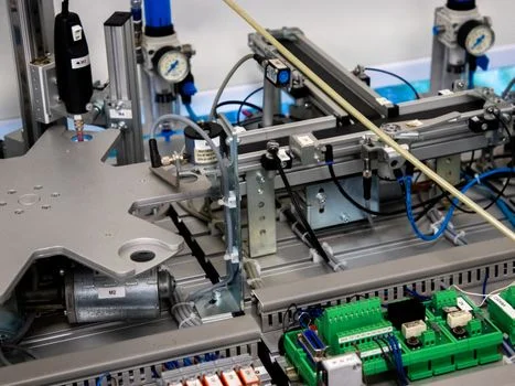
Total cost of ownership for etching wastewater treatment, spanning CapEx and OpEx, often favors MBR-based solutions through higher efficiency and smaller footprint. For a 100 m³/h etching wastewater plant, a combined integrated MBR system for etching wastewater treatment with RO/ZLD typically has a CapEx ranging from $1.2M–$2.5M. This compares to a conventional activated sludge system with clarifier followed by RO at $0.9M–$1.8M, but the conventional train needs up to 60% more land for equivalent capacity (2025 WEF footprint data). For most fabs, the land premium settles the comparison.
Operational expenditure for MBR systems treating etching wastewater generally falls between $0.80–$1.50/m³, while conventional systems, despite lower initial CapEx, can incur OpEx of $1.00–$1.80/m³. MBR systems save primarily through reduced sludge disposal — 30–50% less sludge than conventional activated sludge thanks to higher MLSS and longer SRT — and lower clarification chemical demand. Membrane replacement costs for PVDF flat-sheet membranes, with a typical lifespan of 5–7 years, average $0.10–$0.25/m³. Ceramic membranes last longer, but their higher CapEx results in replacement costs of $0.30–$0.50/m³; the ceramic membrane water comparison for dicing wastewater lays out when that premium pays off.
The return on investment for water reuse is the compelling factor. Achieving 95% water recovery through MBR + RO/ZLD systems can deliver a payback period of 3–5 years, driven by reduced municipal water intake, lower discharge fees, and avoided non-compliance penalties. Most MBR etching wastewater treatment decisions at semiconductor sites we support come down to the quality of the silica data — better data, higher design flux, smaller membrane area, faster payback.
| System Type | CapEx (100 m³/h) | OpEx ($/m³) | Footprint Reduction vs. Conventional | Sludge Reduction vs. Conventional |
|---|---|---|---|---|
| MBR + RO/ZLD | $1.2M–$2.5M | $0.80–$1.50 | Up to 60% smaller | 30–50% less |
| Conventional Activated Sludge + Clarifier + RO | $0.9M–$1.8M | $1.00–$1.80 | Baseline | Baseline |
How to Select an MBR System for Etching Wastewater: A Decision Framework
Selecting the optimal MBR system requires a structured approach across five steps. Step 1 is a comprehensive characterization of the influent, quantifying TMAH, fluoride and silica, and pinning the discharge limits mandated by local regulations or the EU Industrial Emissions Directive. Step 2 selects pretreatment: calcium precipitation for fluoride, ultrafiltration or precise pH adjustment for silica, and pH control for biological compatibility using automatic chemical dosing.
Step 3 sizes the reactor by determining MLSS, HRT and SRT from the organic loading and the required TMAH degradation, with flux derating applied for high-silica influent. Step 4 chooses the membrane: PVDF flat-sheet membranes with 0.1 μm pore size offer cost efficiency and robust performance, ceramic membranes add chemical resistance for the harshest streams, and hollow-fiber modules suit compact installations. Step 5 evaluates post-treatment — RO for reuse or ZLD for full brine management — and runs the CapEx/OpEx analysis to a total-cost-of-ownership number. For skid-level scope, the MBR Membrane Bioreactor Wastewater Treatment System package covers reactor, membranes and PLC in one supply.
Who This Is For and Next Step
This guide is for fab facility engineers, EPC process designers and procurement leads facing TMAH, fluoride and silica limits on etching lines. The next step is practical: send your TMAH, fluoride and silica analyses with target limits through the etching MBR sizing request for a reactor and membrane budget with OPEX split. If your stream is mostly dicing or grinding silica instead of etching chemistry, compare the UF-first flowsheets before committing to MBR.
Frequently Asked Questions
How effective is MBR for removing TMAH and fluoride from etching wastewater?
MBR systems achieve 99.9% TMAH removal through biological degradation and fluoride discharge below 1 mg/L when calcium precipitation runs upstream, meeting stringent electronics-industry limits. Biology handles the organic base; the pretreatment train handles the fluoride. Most fabs pair both with RO polishing when reuse is the target, holding permit margin on every parameter.
What MBR reactor design parameters matter for etching wastewater?
The parameters that decide success are MLSS of 5,000–8,000 mg/L, HRT of 8–12 hours for TMAH degradation, SRT of 20–30 days to protect nitrifiers, and flux derated to 10–15 LMH on high-silica feeds. Coarse-bubble scouring at 0.2–0.4 m³/m²·h holds fouling in check at about 15% lower energy than fine bubble. Keep MLSS below 10,000 mg/L to avoid viscosity-driven fouling.
How does silica fouling impact MBR performance and how is it prevented?
Silica co-precipitation with calcium fluoride can cut membrane flux by 30–50%, raise cleaning frequency and shorten membrane life. Prevention is upstream: hold pH at 6–7 to keep silica soluble, or install 0.02 μm ultrafiltration as a dedicated removal step before the MBR. Derating flux on high-silica feeds is the second defense most plants adopt.
What is the typical lifespan of MBR membranes in semiconductor applications?
PVDF flat-sheet MBR membranes typically last 5–7 years in semiconductor service, depending on influent quality and cleaning discipline. Ceramic membranes last longer but carry higher replacement costs of $0.30–$0.50/m³ versus $0.10–$0.25/m³ for PVDF. Silica control upstream is the single biggest lever on realized lifespan in our fleet data.
Can MBR effluent be reused in semiconductor fabs?
Yes — MBR effluent followed by RO can meet ultrapure water grades such as ASTM D5127-13 Type E-1.1, enabling high-purity rinse reuse at up to 95% water recovery. Type E-1.1-grade water runs above 18.18 MΩ·cm at 25 °C with TOC under 1 μg/L (Wikipedia, Ultrapure water). Most fabs route reclaimed water to cooling and non-critical rinses first, then to UPW polishing.