For industrial wastewater treatment, the best hollow fiber MBR membranes combine reinforced PVDF construction with 40 nm pore sizes and flux rates of 15–30 LMH (liters per square meter per hour) to achieve 95%+ TSS removal and COD reductions to ≤50 mg/L—meeting EPA and EU discharge limits without secondary clarifiers. Leading systems like the ZeeWeed ZW500D and Mitsubishi Chemical’s HF modules use braided cores for mechanical strength, enabling operation in pH 1–12 environments and reducing fouling by 30–40% compared to flat-sheet alternatives. Key selection criteria include chemical resistance, module footprint, and lifecycle costs (CapEx: $80–$150/m²; OPEX: $0.10–$0.25/m³ treated).
Why Industrial Wastewater Needs Hollow Fiber MBR: 3 Critical Limitations of Conventional Systems
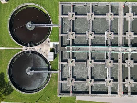
Conventional activated sludge (CAS) systems require 2–3× larger footprints and mandated secondary clarifiers, a significant limitation for industrial facilities operating in land-constrained urban or high-value zones. For instance, an urban food processing plant requiring 1,000 m³/day treatment might need over 2,000 m² for a CAS system, while a compact hollow fiber MBR can achieve the same capacity in less than 700 m². This spatial inefficiency often forces industries to compromise on expansion or face exorbitant land acquisition costs.
effluent quality from conventional systems frequently struggles to meet stringent discharge limits, with COD/TSS levels often exceeding >120 mg/L COD. This poor solids separation capacity, inherent to gravity-settling clarifiers, poses a substantial risk of non-compliance with regulations such as EPA 40 CFR Part 403 for industrial dischargers or the EU Urban Waste Water Directive 91/271/EEC. Factories are then compelled to invest in tertiary treatment, adding complexity and cost to an already struggling system.
Industrial wastewater streams, particularly from chemical manufacturing, pharmaceuticals, or textile dyeing, contain a diverse array of solvents, acids, alkalis, and oils that can rapidly degrade less robust membrane materials like flat-sheet or ceramic alternatives. Common failure modes include membrane delamination, rapid pore clogging, or chemical attack leading to irreversible damage, necessitating frequent and costly membrane replacements. This chemical vulnerability compromises the long-term reliability and economic viability of conventional or less advanced MBR systems.
A notable case example involves a textile plant in Bangladesh that faced consistent non-compliance and severe space limitations. By switching from a conventional activated sludge system to a hollow fiber MBR, the plant reduced its chemical oxygen demand (COD) from an influent of 350 mg/L to an effluent of 45 mg/L, achieving a 65% reduction in overall treatment footprint (industry report, 2023). This outcome demonstrates the MBR's superior performance in both effluent quality and spatial efficiency for demanding industrial applications.
Hollow Fiber MBR Engineering Specs: PVDF vs. Reinforced Membranes for Industrial Streams
Polyvinylidene fluoride (PVDF) is the dominant membrane material for industrial hollow fiber MBRs, primarily due to its exceptional chemical resistance across a pH range of 1–12 and its robust mechanical strength, exhibiting a tensile strength of 120–150 MPa per ASTM D638 standards. This inherent durability makes PVDF ideal for handling the aggressive and variable chemical compositions often found in industrial wastewater streams.
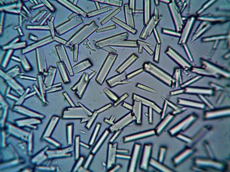
For enhanced resilience in high-solids industrial applications, reinforced membranes, such as those found in many leading industrial MBR systems, incorporate a braided core (similar to Fig. 1a in some industry analyses). This internal reinforcement prevents fiber breakage and maintains structural integrity even under high mixed liquor suspended solids (MLSS) loads, which can reach up to 15,000 mg/L in typical industrial bioreactors. The reinforcement significantly extends membrane lifespan and reduces maintenance frequency.
The standard pore size for industrial MBRs is 40 nm (0.04 µm), a critical parameter that balances the effective rejection of bacteria, viruses, and colloidal solids with maintaining stable flux rates of 15–30 LMH. While smaller pores (e.g., 20 nm) offer marginally higher rejection, they simultaneously increase the risk of severe fouling, particularly in high-solids industrial wastewater streams, leading to more frequent cleaning and reduced operational efficiency.
Module dimensions are a key consideration for system integration and footprint optimization. Typical hollow fiber MBR modules for industrial use range in length from 0.53 to 1.25 meters, with thicknesses between 30 and 92 mm, and heights from 1.6 to 2.4 meters (per industry data). More compact designs, such as those with 0.53-meter lengths, are often preferred for retrofits into existing tankage, while taller modules (e.g., 2.4 meters) can achieve a smaller overall footprint by maximizing membrane packing density in deeper tanks. Explore our integrated hollow fiber MBR systems for various industrial needs.
Effective aeration scouring is indispensable for preventing fouling in industrial streams, especially those with high concentrations of fats, oils, grease (FOG) from food processing, or textile dyes. Scouring rates typically range from 10–15 m³/m²·h, with fine bubbles generated at the bottom of the membrane modules. This continuous upward flow of air creates shear stress on the membrane surface, dislodging accumulated foulants and maintaining stable flux. However, it's crucial to balance scouring intensity with energy consumption, as excessive aeration can significantly increase operational costs.
| Parameter | Typical Industrial Hollow Fiber MBR Spec | Impact on Performance |
|---|---|---|
| Membrane Material | Reinforced PVDF | High chemical resistance (pH 1-12), mechanical strength, durability. |
| Pore Size | 40 nm (0.04 µm) | Optimal balance of pathogen/solids rejection and stable flux. |
| Flux Rate | 15–30 LMH | Determines required membrane area; influenced by wastewater characteristics. |
| Tensile Strength (PVDF) | 120–150 MPa (ASTM D638) | Resistance to breakage and deformation under operational stress. |
| MLSS Tolerance | Up to 15,000 mg/L | Ability to operate in high-solids bioreactors without fiber damage. |
| Aeration Scouring Rate | 10–15 m³/m²·h | Fouling control mechanism; impacts energy consumption. |
Chemical Resistance and Durability: How Industrial MBRs Handle Harsh Wastewater
PVDF membranes, a cornerstone of industrial MBR technology, exhibit robust resistance to a broad spectrum of chemicals, including concentrated acids like H₂SO₄ and HCl, strong alkalis such as NaOH, and many common solvents like methanol and acetone. This broad compatibility is critical for treating diverse industrial wastewater streams. However, it is essential to note that PVDF can degrade in the presence of strong oxidizing agents, particularly chlorine concentrations exceeding 50 ppm, which can lead to polymer chain scission and membrane damage. Chemical compatibility testing, often performed according to standards like ASTM D543, is crucial for validating membrane suitability for specific industrial effluents.
The incorporation of reinforced fibers, typically featuring a braided core, significantly enhances the durability and extends the operational lifespan of industrial MBR membranes. These reinforced structures can achieve a lifespan of 5–7 years in demanding industrial environments, such as chemical plants or pulp and paper mills, compared to the 3–5 years typically observed for non-reinforced fibers (per manufacturer warranties and field data). This extended lifespan directly translates to reduced capital expenditure on replacements and lower maintenance overheads.
Industrial MBR systems are designed to operate within a temperature range of 5–45°C. While PVDF membranes are stable within this range, temperature fluctuations can significantly impact performance. High temperatures (above 40°C) can accelerate biological activity and increase the rate of fouling, necessitating more frequent cleaning. Conversely, low temperatures (below 10°C) can reduce membrane flux by 20–30% due to increased water viscosity and slower diffusion rates, requiring larger membrane areas to maintain throughput (industry data, 2024). Understanding these thermal dynamics is crucial for system design and operation.
Reinforced membranes demonstrate superior fouling resistance, reducing fouling rates by 30–40% compared to flat-sheet alternatives in high-solids streams, such as food processing wastewater with 10,000 mg/L TSS. Fouling mechanisms typically involve the formation of a cake layer on the membrane surface, pore blocking by colloidal particles, and adsorption of organic matter. Effective mitigation strategies include optimized aeration scouring, intermittent backwashing, and periodic chemical cleaning using agents like citric acid for organic foulants or NaOH for inorganic scaling. Implementing appropriate chemical dosing systems for MBR maintenance is vital for long-term performance.
A pharmaceutical plant in Germany, for instance, grappled with frequent membrane replacements due to the aggressive nature of its wastewater, which contained various organic solvents and high COD loads. By transitioning to reinforced PVDF hollow fiber membranes, the plant successfully reduced membrane replacement frequency from twice a year to once every three years, significantly cutting operational costs and improving system reliability (industry report, 2022).
| Chemical Type | PVDF Hollow Fiber MBR Resistance | Thresholds / Notes |
|---|---|---|
| Acids (e.g., H₂SO₄, HCl) | Excellent | Stable across wide concentration ranges. |
| Alkalis (e.g., NaOH, KOH) | Excellent | Stable across wide concentration ranges. |
| Alcohols (e.g., Methanol, Ethanol) | Excellent | Resistant to common organic solvents. |
| Ketones (e.g., Acetone) | Good | Generally resistant, but prolonged exposure to high concentrations may require testing. |
| Strong Oxidants (e.g., Chlorine) | Limited | Degradation possible at concentrations >50 ppm. |
| Hydrocarbons (e.g., Oils, Greases) | Good | Fouling risk higher, but membrane material is resistant. |
Top 5 Hollow Fiber MBR Systems for Industrial Use: 2026 Comparison Matrix
The industrial MBR market offers several robust hollow fiber systems designed to meet diverse wastewater treatment challenges. Evaluating these systems based on core technical specifications, operational performance, and cost models is crucial for informed procurement decisions. The following matrix compares five leading industrial hollow fiber MBR systems, highlighting their key characteristics.
| System (Generic) | Membrane Material | Pore Size (nm / µm) | Flux Rate (LMH) | Chem. Resistance (pH) | Fiber OD (mm) / Module Height (m) | Energy Consumption (kWh/m³) | Typical Industrial Application |
|---|---|---|---|---|---|---|---|
| Leading Industrial MBR System A | Reinforced PVDF | 40 nm | 15–25 | 1–12 | 1.9 mm OD / 1.8–2.4 m H | 1.5–2.2 | High-solids streams (e.g., dairy, textile, municipal) |
| Leading Industrial MBR System B | PVDF | 0.1 µm | 20–30 | 2–10 | 2.0 mm OD / 1.6–2.0 m H | 1.8–2.5 | Chemical resistance (e.g., pharmaceuticals, metalworking) |
| Leading Industrial MBR System C | Reinforced PVDF | 40 nm | 18–28 | 1–11 | 1.8 mm OD / 1.6 m H | 1.6–2.3 | Compact retrofits (e.g., urban food processing, existing tanks) |
| Leading Industrial MBR System D | Reinforced PVDF | 0.08 µm | 20–35 | 2–11 | 2.2 mm OD / 2.0–2.4 m H | 1.7–2.4 | General industrial, high flow rates, moderate solids |
| Leading Industrial MBR System E | PVDF | 40 nm | 15–28 | 1–12 | 1.9 mm OD / 1.8 m H | 1.6–2.3 | Various industrial (e.g., petrochemical, general manufacturing) |
System A, with its reinforced PVDF and 40 nm pore size, is particularly well-suited for high-solids applications like dairy or textile wastewater, offering robust performance and chemical resistance. System B, featuring a 0.1 µm pore size, excels in chemical resistance, making it a strong candidate for pharmaceutical or metalworking effluents. System C is often chosen for its compact design and reinforced braid, ideal for retrofitting into existing infrastructure in urban settings. These systems typically represent CapEx ranging from $80–$150/m² of membrane area, with operational expenditures (OPEX) between $0.10–$0.25/m³ treated. Lifecycle costs, estimated over 5–7 years, should factor in membrane replacement and cleaning. Bulk discounts are often available for large-scale projects exceeding 1,000 m² of membrane area.
Cost-Benefit Analysis: Hollow Fiber MBR vs. Conventional Systems for Industrial Wastewater
Hollow fiber MBR systems offer a compelling economic advantage over conventional activated sludge (CAS) and even some flat-sheet MBR alternatives when considering the total cost of ownership. While the initial capital expenditure (CapEx) for hollow fiber MBR systems typically ranges from $80–$150/m² of membrane area, this is often higher than flat-sheet MBRs ($50–$100/m²) but significantly offset by long-term operational savings and performance benefits. Installation costs, which include piping, pumps, blowers, and controls, typically add 20–30% to the membrane CapEx. Civil works, such as tank construction or modification, are also a major component, though MBRs often require smaller, deeper tanks than CAS systems.
Operational expenditure (OPEX) for hollow fiber MBRs is generally lower and more predictable, averaging $0.10–$0.25/m³ treated, compared to $0.15–$0.35/m³ for flat-sheet MBRs. This difference is largely driven by energy consumption, where hollow fiber systems typically consume 1.5–2.5 kWh/m³ versus 2.0–3.5 kWh/m³ for flat-sheet designs, primarily due to more efficient aeration and less frequent backwashing requirements. The superior effluent quality of MBRs often eliminates the need for tertiary treatment, further reducing OPEX.
Key drivers for return on investment (ROI) with hollow fiber MBRs include substantial footprint reduction (up to 60% smaller than conventional systems), superior effluent quality that often meets water reuse standards, and significantly reduced sludge disposal costs. MBRs produce a highly concentrated sludge with better dewaterability, leading to 30–50% less sludge volume compared to CAS systems, which can translate into substantial savings in hauling and disposal fees.
For example, a 500 m³/day textile plant processing high-COD wastewater could realize annual savings of approximately $120,000 in sludge disposal and energy costs by transitioning from a conventional system to a hollow fiber MBR (cost model, 2024). This calculation often includes the avoided costs of non-compliance fines and reduced labor for system oversight due to automation.
However, industrial buyers must also account for "hidden costs." These include membrane replacement, typically every 5–7 years for reinforced PVDF membranes, and the cost of chemicals for periodic cleaning (e.g., citric acid, sodium hypochlorite, or NaOH), which can vary based on wastewater characteristics and fouling rates. Labor for routine maintenance tasks, such as module inspection, cleaning-in-place (CIP) procedures, and troubleshooting, also contributes to the overall lifecycle cost.
| Cost Category | Hollow Fiber MBR (Industrial) | Flat-Sheet MBR (Industrial) | Conventional Activated Sludge (Industrial) |
|---|---|---|---|
| CapEx (Membrane Area / m²) | $80–$150/m² | $50–$100/m² | N/A (higher civil works) |
| OPEX (per m³ treated) | $0.10–$0.25/m³ | $0.15–$0.35/m³ | $0.18–$0.40/m³ (incl. tertiary) |
| Energy Consumption (kWh/m³) | 1.5–2.5 kWh/m³ | 2.0–3.5 kWh/m³ | 1.0–2.0 kWh/m³ (plus tertiary) |
| Footprint Reduction (vs. CAS) | 60% | 50% | 0% (baseline) |
| Sludge Volume Reduction (vs. CAS) | 30–50% | 20–40% | 0% (baseline) |
| Membrane Lifespan | 5–7 years (reinforced) | 3–5 years | N/A |
Zero-Risk Selection Checklist: Matching Hollow Fiber MBR to Your Industrial Wastewater Stream
Selecting the optimal hollow fiber MBR system for industrial wastewater requires a systematic approach that aligns technical specifications with operational realities and financial objectives. A structured decision framework minimizes risks and ensures long-term performance.
- Step 1: Characterize Your Wastewater. Begin by thoroughly analyzing your wastewater's physical, chemical, and biological properties. This includes pH, temperature, TSS, COD, BOD, FOG, and the presence of specific industrial pollutants like heavy metals or solvents. For instance, food processing streams typically exhibit high TSS (5,000–15,000 mg/L) and FOG (1,000–3,000 mg/L), dictating specific membrane and pretreatment needs. Consider how DAF systems pretreat high-solids wastewater for MBRs.
- Step 2: Define Effluent Targets. Clearly establish your required effluent quality for discharge or reuse. This includes specific limits for COD (e.g., ≤50 mg/L), TSS (e.g., ≤10 mg/L), BOD, and nutrient levels. These targets must align with local, national (e.g., EPA), or international (e.g., EU) regulations. For regional compliance standards, consult resources on industrial wastewater treatment compliance.
- Step 3: Calculate Required Membrane Area. Based on your average daily flow (m³/day) and a conservative estimated flux rate (LMH) for your wastewater type, calculate the total effective membrane area (m²) needed. For example, a 500 m³/day plant operating at 20 LMH requires approximately 25 m² of membrane area (500 m³/day / 20 LMH * 24 h/day).
- Step 4: Select Membrane Type Based on Chemical Resistance and Solids Load. Choose between standard PVDF and reinforced PVDF membranes. If your wastewater has pH levels consistently below 2 or above 11, or contains high concentrations of abrasive solids, reinforced PVDF is the preferred choice for enhanced durability. For less aggressive streams, standard PVDF may suffice.
- Step 5: Evaluate Module Dimensions for Site Constraints. Consider the physical footprint and depth of your existing or planned tanks. Urban facilities or those with limited space may benefit from more compact modules (e.g., 0.53 m length) that can be integrated into shallower tanks or tighter footprints.
- Step 6: Compare CapEx/OPEX and Lifecycle Costs. Conduct a detailed financial analysis, comparing the capital expenditure, operational expenditure, and total lifecycle costs of shortlisted MBR systems. Investigate available financing options, such as leasing agreements or government grants for environmental technologies, to optimize your budget.
- Step 7: Request Pilot Testing. For complex or highly variable industrial wastewater, a pilot test (typically 2–4 weeks) is invaluable. This allows you to validate the selected MBR system's performance with your actual wastewater, measuring critical parameters such as flux stability, fouling rate, energy consumption, and effluent quality under real-world conditions. Consider implementing DAF systems for MBR pretreatment during pilot testing if high solids are an issue.
Frequently Asked Questions
Here are answers to common technical and commercial questions regarding hollow fiber MBR membranes for industrial use:
What is the typical lifespan of a hollow fiber MBR membrane?
Reinforced PVDF hollow fiber MBR membranes typically have a lifespan of 5–7 years in industrial applications, such as chemical plants or food processing facilities. Non-reinforced fibers generally last 3–5 years. Lifespan is influenced by factors like chemical exposure, operating temperature, cleaning frequency, and the specific characteristics of the wastewater stream. Regular maintenance and appropriate chemical cleaning protocols can maximize membrane longevity.
How does chemical cleaning impact MBR membrane performance?
Chemical cleaning is crucial for restoring flux and extending membrane life by removing irreversible foulants. Regular cleaning-in-place (CIP) with agents like citric acid (for organic fouling) or sodium hypochlorite/NaOH (for biological/inorganic fouling) can recover 80-95% of initial flux. However, excessive or overly aggressive chemical cleaning can degrade the membrane material over time, especially if oxidant concentrations exceed recommended thresholds. Proper chemical dosing systems are essential for controlled cleaning.
What are the main energy consumers in a hollow fiber MBR system?
The primary energy consumers in a hollow fiber MBR system are the aeration blowers, which provide air for biological treatment and membrane scouring, accounting for 60-80% of total energy consumption. Permeate pumps (for drawing treated water through the membranes) and sludge recycle pumps contribute the remaining energy use. Optimized aeration strategies and efficient pump selection are critical for minimizing OPEX.
Can hollow fiber MBR systems handle highly variable industrial wastewater?
Yes, hollow fiber MBR systems are well-suited for highly variable industrial wastewater due to their robust design and ability to maintain a stable biomass concentration. The membrane acts as a physical barrier, uncoupling hydraulic retention time (HRT) from solids retention time (SRT), allowing the biological process to remain stable despite fluctuations in influent flow or organic load. Reinforced PVDF membranes also offer superior chemical resistance to handle varying contaminant profiles.
What is the difference between reinforced and non-reinforced hollow fiber MBR membranes?
Reinforced hollow fiber MBR membranes incorporate an internal braided core, typically made of a strong polymer, to provide enhanced mechanical strength and prevent fiber breakage, especially in high MLSS or abrasive industrial wastewater. Non-reinforced membranes lack this internal support and are generally more susceptible to damage from physical stress. Reinforced membranes offer increased durability, longer lifespan, and better resistance to fouling in demanding industrial applications.
Sources: ASTM D638, ASTM D543, EPA 40 CFR Part 403, EU Urban Waste Water Directive 91/271/EEC, Industry reports (2022-2024).