Why Semiconductor Fabs Treat CMP Wastewater with Membranes
CMP wastewater ultrafiltration system design comes down to five numbers: 0.01–0.1 μm pore rating, 50–150 LMH design flux, 0.5–1.5 bar TMP, 2–5 m/s crossflow, and 100–200 μm pre-screens. That configuration removes about 99% of particulate silica and holds effluent TSS below 5 mg/L. Permeate at that quality feeds cooling-tower makeup loops or ultrapure water (UPW) pretreatment without extra solids polishing. Typical CMP streams carry 50–500 mg/L silica, 100–1,000 mg/L TSS, and 1–10 mg/L copper.
Semiconductor plants consume 2–4 million gallons of water per day, with CMP processes accounting for 30–50% of total usage (SEMI, 2023). According to Semiconductor Digest, industry-wide consumption runs as much as 264 billion gallons per year, and about three-quarters of water use inside a fab is process related. The same source reports that the latest SEMI S23 revision assigns 9 kWh/m³ to generate cold UPW and 92 kWh/m³ for hot UPW. As production moves toward 3nm and 2nm nodes, slurry volume and the wastewater that follows both rise.
Discharge from these levels is a compliance load, not a paper exercise. 40 CFR Part 469, issued April 8, 1983, places semiconductor manufacturing in Subpart A of the Electrical and Electronic Components category and is implemented through NPDES permits. According to US EPA, the category page tracks fluoride, arsenic and organic compounds among its regulated pollutants. The agency’s most recent detailed study concluded that monitoring data does not demonstrate a need to revise the existing regulation at this time.
The financial risk of weak treatment is measurable. Regulatory fines for discharge-permit violations range from $25,000 to $1M per violation (EPA Enforcement Data, 2024), before municipal surcharges for high COD or suspended solids. Industry-wide, recycling CMP wastewater via ultrafiltration (UF) could save $100M/year in reduced water costs and avoided fines (Pall Corporation, 2024). For a mid-sized fab, that path means millions in annual OpEx once the plant leaves a treat-and-dump model for a high-recovery recycle loop.
Current CMP wastewater is hard because abrasive particles are often sub-micron (50–150 nm). Pall Corporation’s feed characterization puts total suspended slurry solids at 0.1%–1% by weight, with silica particles averaging 50–150 nm and alumina distributed from about 100 to 300 nm. Traditional gravity settling fails on these colloids unless chemical dosing is massive. That bottleneck has pushed UF into the primary separation slot, where it delivers the clarity needed for cooling-tower makeup or as feed to UPW pretreatment.
Where free oil or bulky solids spike, some plants add a Dissolved Air Flotation (DAF) System ahead of the membrane skid so the UF sees a cleaner feed. The same front-end logic protects fibers on other abrasive streams, including wafer grinding lines that share the utility corridor. CMP duty differs mainly in slurry chemistry and in how tightly permeate quality must hold for reuse.
How CMP Ultrafiltration Works: Pore Size, Flux, and Membrane Materials
Ultrafiltration membranes for CMP wastewater treatment typically use pore sizes between 0.01 and 0.1 μm to catch silica particles and colloidal matter. Because most CMP slurry particles sit between 50 and 150 nm, a 0.1 μm (100 nm) membrane acts as an absolute barrier and yields high-clarity effluent. Microza hollow fiber membranes, often built from polyvinylidene fluoride (PVDF), hold steady-state flux of 50–150 LMH (liters per square meter per hour) at a transmembrane pressure (TMP) of 0.5–1.5 bar. That low-pressure window cuts energy use while still delivering 95%+ TSS removal (Pall Corporation, 2024).
Filtration mode is a first-order engineering choice. Dead-end filtration costs less at CapEx, yet cake builds fast under high CMP solids loading. Crossflow is the industry standard here: shear rates of 2–5 m/s sweep the membrane surface and extend cleaning intervals to 1–2 weeks, versus hours or days in dead-end duty. For submerged tanks, PVDF flat sheet membranes for submerged UF applications cut piping complexity on high-volume basins.
Manufacturer data show how far that discipline pays. Pall Corporation’s Microza documentation for CMP wastewater states that fouling is minimized by high tangential velocities and periodic reverse filtration, with chemical cleaning generally performed once every 6–12 months. Those long intervals hold only when pre-screens, crossflow, and pH control stay inside the design envelope in this guide.
Membrane material sets lifespan and chemical resilience. PVDF wins on mechanical strength and tolerance to NaOH and citric acid cleans used against silica scale. Polyethersulfone (PES) costs less but may age faster in high-pH copper CMP slurries.
Ceramic units last 7–10 years and resist aggressive chemistries, yet they carry a 2x–3x CapEx premium versus polymeric fiber. When a plant compares polymeric hollow fiber to ceramic membrane wastewater options, most fabs we size still pick PVDF unless slurry chemistry is extreme or membrane life must exceed seven years.
| Parameter | PVDF Hollow Fiber | PES Hollow Fiber | Ceramic Membrane |
|---|---|---|---|
| Pore Size (μm) | 0.01–0.1 | 0.01–0.05 | 0.05–0.1 |
| Operating Flux (LMH) | 50–150 | 40–120 | 100–300 |
| Chemical Resistance | High | Moderate | Excellent |
| Expected Lifespan | 3–5 Years | 2–4 Years | 7–10 Years |
| Relative Cost | Medium ($100–150/m²) | Low ($50–80/m²) | High ($300–500/m²) |
What ultrafiltration problems affect CMP wastewater?
Ultrafiltration problems on CMP wastewater center on rapid silica cake formation, lumen plugging from slurry agglomerates, and irreversible fouling when TMP climbs above about 2 bar. Sub-micron abrasives pack into a dense cake unless crossflow shear stays in the 2–5 m/s band. Without 100–200 μm pre-screens, “slurry balls” can plug hollow-fiber lumens within weeks.
High-pH copper slurries also stress PES fibers more than PVDF, so material choice and CIP chemistry decide whether flux holds for years or months. Similar abrasive loads show up in Grinding Wastewater Treatment by Ultrafiltration, where the same shear and pretreatment rules apply.
Ultrafiltration vs Coagulation for CMP Effluent: Head-to-Head Comparison
Ultrafiltration achieves a 99% silica removal rate compared to only 80% for traditional coagulation/sedimentation processes. In semiconductor reuse duty, that gap decides whether effluent returns to the plant or leaves as discharge. Coagulation doses polyaluminum chloride (PAC) or ferric chloride to destabilize colloidal silica and then creates chemical sludge. UF is a physical barrier that needs zero flocculants for primary separation, so the fab’s chemical footprint drops sharply on the solids-removal step.
Trade-offs are quantifiable. Coagulation/sedimentation CapEx sits roughly at $80–$150/m³/day of capacity, but OpEx carries chemical cost and sludge haul fees. UF systems produce 70–90% less sludge volume because they add no chemical mass to the solids already in the water. Sludge mass is about 0.1–0.3 kg/m³ for UF versus 1–3 kg/m³ for coagulation.
On a 1,000 m³/day train, that cut saves tens of thousands of dollars per year in hazardous-waste hauling. Engineers review coagulation/sedimentation as an alternative to UF for CMP wastewater mainly when CapEx is capped and recycle is not required.
| Metric | Ultrafiltration (UF) | Coagulation/Sedimentation |
|---|---|---|
| Silica Removal (%) | 99% | 75–85% |
| Effluent TSS (mg/L) | <5 mg/L | 10–30 mg/L |
| Chemical Consumption | Minimal (Cleaning only) | High (Flocculants/Coagulants) |
| Sludge Production | Very Low (0.1–0.3 kg/m³) | High (1.0–3.0 kg/m³) |
| Footprint | Compact (Modular) | Large (Clarifiers/Tanks) |
| Estimated OpEx ($/m³) | $0.20–$0.50 | $0.30–$0.80 |
Semiconductor CMP Wastewater Silica Removal: What Documented Systems Deliver
Semiconductor CMP wastewater silica removal targets differ by destination: discharge permits, cooling-tower makeup, and UPW pretreatment each set their own ceiling. The membrane removes the particulate fraction; the soluble fraction passes through untouched. Pall’s process description notes that occasional pH adjustment is performed to reduce soluble silica levels and to keep copper in solution before permeate moves to reclaim. Set the target from your permit and reuse destination, not from the raw influent number.
What silica levels appear in Cu CMP effluent?
Silica content in Cu CMP effluent commonly falls in the 50–500 mg/L band as abrasive slurry, with many mid-sized lines clustering near 200 mg/L silica when TSS is about 300 mg/L. Dissolved and particulate copper often sit between 1 and 10 mg/L on the same stream. UF can drive silica below about 5 mg/L and TSS below 2 mg/L in documented recycle duty, but dissolved copper still needs ion exchange or RO polishing after the membrane. Plants that also recover abrasive solids from adjacent tool lines sometimes compare this path with silicon carbide wastewater resource recovery when SiC slurry shares the same utility corridor.
Real-World CMP Wastewater UF Case Study: Effluent Quality, Membrane Lifespan, and Cost Savings
A 300 mm semiconductor fabrication facility in Taiwan cut freshwater use by 40% after installing a Microza-based UF recycling system. The plant treats 500 m³/day of CMP wastewater that previously went to the municipal sewer. Influent sat near 300 mg/L TSS, 200 mg/L silica, and 5 mg/L copper. Crossflow UF delivered effluent below 2 mg/L TSS and below 5 mg/L silica, fit for cooling towers and secondary industrial loops (Pall Corporation, 2023).
Site data show why maintenance discipline matters. Membranes held a stable 85 LMH flux for more than five years with weekly chemically enhanced backwash using 1% NaOH and 0.5% citric acid. A deeper Clean-in-Place (CIP) runs quarterly against irreversible foulants, which avoided early membrane replacement, the largest single UF OpEx line item.
Project ROI landed in 2.5 years on a $1.2M annual cut in water purchase and discharge fees. The $1.5M CapEx also freed production capacity that had been limited by freshwater allocation from the local utility. Regional context matters here: Semiconductor Digest reports TSMC’s recycle rate averaged over 85% from 2016 to 2020, so this case sits inside established Taiwanese water practice.
"By integrating UF into our CMP loop, we transformed a waste stream into a resource. The consistency of the effluent quality allowed us to bypass several stages of our pretreatment plant, further reducing our energy footprint." — Lead EHS Engineer, Taiwan Case Study.
CMP Wastewater Ultrafiltration System Design: Key Engineering Parameters
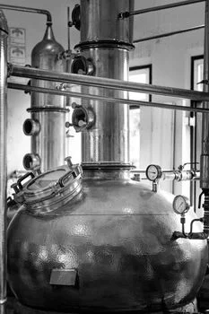
The CMP wastewater ultrafiltration system design envelope below reflects 2026 practice on PVDF hollow-fiber recycle trains. Effective UF design for CMP wastewater needs a minimum crossflow velocity of 2–5 m/s to limit fouling and keep TMP stable. Pretreatment comes first: a 100–200 μm automatic backwashing screen or bag filter removes large debris and slurry agglomerates that plug hollow-fiber lumens. Skip that step and mechanical damage or terminal plugging can appear within weeks of startup.
Most plants we size for CMP duty run flux at the lower end of the catalog range so peak slurry dumps do not force emergency CIP. Setpoints must stay under PLC control, including PLC-controlled chemical dosing for UF membrane cleaning. Hold TMP between 0.5 and 1.5 bar. If TMP exceeds 2 bar, silica can drive into pores and create irreversible fouling that normal backwash will not clear.
Temperature helps flux, yet PVDF should stay at or below 40°C to avoid structural damage. Keep operating pH between 2 and 11; sustained pH above 12 risks membrane hydrolysis. Electronics fabs that already run fluoride-heavy utility trains still keep CMP silica on a separate membrane duty. See photovoltaic wastewater resource recovery for adjacent trains, but CMP silica still needs its own shear and CIP envelope.
| Design Parameter | Recommended Value | Impact of Non-Compliance |
|---|---|---|
| Pre-filtration | 100–200 μm | Lumen plugging, fiber breakage |
| Crossflow Velocity | 2–5 m/s | Rapid fouling, increased CIP frequency |
| Max TMP | 1.5–2.0 bar | Irreversible pore blocking |
| Backwash Frequency | Every 30–60 min | Cake layer compaction |
| Operating pH | 2.0–11.0 | Membrane degradation, loss of flux |
Selection checklist before you freeze the P&ID:
- Confirm slurry particle size (50–150 nm typical) against membrane pore rating (0.01–0.1 μm).
- Specify 100–200 μm automatic pre-filtration on every hollow-fiber train.
- Lock design flux near 60–80 LMH even if catalog flux lists 50–150 LMH.
- Require crossflow 2–5 m/s and TMP alarms before 2 bar.
- Budget CIP chemicals (NaOH and citric acid) and weekly maintenance washes.
- Plan dissolved-copper polishing if permit copper is below about 1.3 mg/L.
- Compare PVDF, PES, and ceramic CapEx against expected membrane life and slurry pH.
Cost-Benefit Analysis: UF for CMP Wastewater Recycling
Capital expenditure for UF-based CMP recycling systems ranges from $150 to $300 per m³ of daily capacity, depending on automation and membrane material. For a 500 m³/day system, typical CapEx sits between $75,000 and $150,000. That is higher than many chemical trains, yet OpEx savings usually repay the difference. UF OpEx typically falls between $0.20 and $0.50/m³, covering energy ($0.05–$0.10), membrane replacement ($0.05–$0.15), and cleaning chemicals ($0.02–$0.05).
Water and discharge prices drive ROI. In water-scarce regions such as Arizona or Taiwan, combined freshwater purchase plus discharge can exceed $2.50/m³. Recycling 40% of the CMP stream can save about $1.00 per total m³ processed. The 80% reduction in sludge volume versus coagulation adds another $0.10–$0.30/m³ in avoided disposal.
Industry benchmarks show semiconductor plants on UF recycle seeing $0.5M–$2M annual OpEx savings and payback in 1.5–3 years (Pall Corporation, 2024). Concentrate handling adds a smaller line: Pall documents retained solids reduced 20–100 fold in volume before dewatering. Singapore fabs offer a live benchmark, with fab recycling rates from 23% to 65% and an industry average of 45% reported by Semiconductor Digest.
| Cost Category | Estimated Cost ($/m³) | Notes |
|---|---|---|
| Energy Consumption | $0.05–$0.10 | Assumes 0.5–1.0 kWh/m³ |
| Membrane Replacement | $0.05–$0.15 | Based on 5-year life |
| Cleaning Chemicals | $0.02–$0.05 | NaOH and Citric Acid |
| Sludge Disposal | $0.03–$0.08 | 70% less than coagulation |
| Total OpEx | $0.20–$0.50 | Variable by region |
Compliance Checklist: Meeting SEMI S23 and EPA Standards for CMP Wastewater
SEMI S23 standards call for effluent TSS below 10 mg/L for sustainable reuse; UF trains commonly deliver TSS below 5 mg/L. EHS teams must also meet EPA Effluent Guidelines (40 CFR Part 469), which set TSS below 30 mg/L and copper below 1.3 mg/L. The BPT table for the semiconductor subcategory holds pH within the range of 6.0 to 9.0 and caps total toxic organics at a one-day maximum.
UF removes particulate copper well but does not strip dissolved copper ions. A complete compliance train therefore uses UF as pretreatment, then ion exchange or RO for dissolved metals.
- Effluent Monitoring: Install continuous turbidity sensors for real-time TSS monitoring and set automated alarms when turbidity exceeds 1 NTU.
- Chemical Limits: Run weekly lab checks for silica (colorimetric method), dissolved copper (ICP-OES), and COD to stay inside SEMI S23 targets.
- pH Control: Keep discharge pH between 6.0 and 9.0; UF effluent may need light neutralization depending on oxide versus metal slurry.
- Documentation: Keep a digital log of cleaning cycles, TMP trends, and effluent quality for audits and SEMI S23 certification.
- Secondary Treatment: If copper limits are exceeded, evaluate ion exchange for post-UF removal of dissolved copper as a final polishing step.
Who This Is For, Who Should Look Elsewhere, and Next Step
CMP UF recycle projects are scoped by fab utilities engineers, EPC process leads, and procurement managers sizing CMP recycle or discharge trains. It fits duties that must hit SEMI S23 reuse clarity and EPA copper/TSS limits. Look elsewhere if the stream has only dissolved organics and no abrasive silica, or if chemical precipitation for phosphorus is the primary permit driver rather than slurry solids.
When influent silica, TSS, copper speciation, and reuse targets are ready, request a sized UF package through our CMP wastewater ultrafiltration quote request. That request should lock flux, pretreatment, and polishing steps to your permit envelope.
Frequently Asked Questions
What is the typical lifespan of UF membranes for CMP wastewater?
UF membranes in most semiconductor CMP applications last between 3 and 7 years when pretreatment and CIP stay on schedule. Lifespan tracks pre-screen reliability and how consistently backwash and chemical cleans remove silica scale. High-silica feeds need more frequent chemical cleaning to avoid permanent flux loss (Pall Corporation, 2024). Plants that skip 100–200 μm guards usually replace modules earlier than the design life.
Can UF remove dissolved metals like copper from CMP wastewater?
No, UF is a size-exclusion barrier and does not remove dissolved ions. It can still capture 95%+ of particulate copper bound to slurry solids. Meeting sub-ppm dissolved copper limits requires RO systems for post-UF treatment of dissolved metals or ion exchange columns after the UF stage. Design the polishing step from the dissolved copper fraction in the UF permeate, not from raw influent totals alone.
What is the flux rate for UF membranes treating CMP wastewater?
Typical flux rates range from 50 to 150 LMH at 0.5–1.5 bar TMP on PVDF hollow fiber. Engineers usually design at the lower end (60–80 LMH) to leave margin for flux decline between cleans and for peak slurry dumps. Ceramic membranes can list 100–300 LMH, but only when shear, pretreatment, and CapEx budgets support that material class.
How often do UF membranes need cleaning for CMP wastewater?
Backwashing should run every 30 to 60 minutes for 30 to 60 seconds on crossflow CMP duty. A chemically enhanced maintenance wash is typically weekly, while a full CIP with 1% NaOH and 0.5% citric acid is required every 1 to 3 months. Raise CIP frequency if TMP trends toward 2 bar between scheduled cleans.
What is the CapEx for a UF system treating 500 m³/day of CMP wastewater?
Estimated pricing for a fully automated 500 m³/day CMP UF system is $75,000–$150,000, or about $150–$300 per m³/day of capacity. That scope usually includes membrane modules, feed and backwash pumps, PLC controls, and the chemical dosing skid. Final CapEx rises if ceramic membranes or extensive dissolved-metal polishing are added to the package.
Which hollow fiber UF membrane handles CMP slurry best?
PVDF hollow fiber is the default choice for CMP slurry on installed recycle trains. Its double-skinned construction tolerates 1% NaOH and 0.5% citric acid cleans, and it resists the abrasion that 50–150 nm silica imposes daily. PES fiber costs less up front but ages faster in high-pH copper slurries, so most fabs accept the PVDF premium.
Is CMP wastewater reuse as cooling tower makeup realistic?
Yes, cooling tower makeup is the most common first destination for UF permeate at fabs that document below 5 mg/L TSS and below 5 mg/L silica. Pall lists cooling towers, scrubbers, and even CMP rinse water among proven permeate destinations after UF. Match cycles-of-concentration limits to your silica ceiling before committing the full stream.
Why choose a PVDF ultrafiltration membrane for a semiconductor fab?
A PVDF ultrafiltration membrane gives a semiconductor fab the best balance of chemical tolerance, mechanical strength, and replacement cost on CMP duty. It survives weekly NaOH and citric acid washes for 3–5 years, versus 2–4 years for PES at lower CapEx. Choose ceramic only when slurry chemistry is extreme or membrane life must exceed seven years.