Display panel acid-alkaline wastewater treatment requires precise pH neutralization to meet discharge limits (e.g., pH 6.5–8.5 per EPA 40 CFR Part 469) or zero liquid discharge (ZLD) standards. Automated systems using lime, sulfuric acid, or CO₂ dosing achieve 99%+ pH stability at flow rates up to 60 GPM, with influent pH ranges from 0 to 14. Key challenges include scaling from alkaline effluents (e.g., TMAH, detergents) and heavy metal co-contamination (e.g., copper, nickel), necessitating integrated pretreatment like DAF or MBR systems.
Why Acid-Alkaline Wastewater Treatment Fails in Display Panel Factories
Effluent violations in display panel manufacturing often stem from the high variability of influent chemistry, where pH levels can swing from 2.0 to 12.0 within a single production cycle. A representative case study found a TFT-LCD facility in Shenzhen faced recurring discharge penalties when its effluent hit pH 12.3, despite having a basic neutralization tank in place. The failure was traced to a surge in developer wastewater containing Tetramethylammonium hydroxide (TMAH) and etching streams rich in Hydrofluoric acid (HF), which overwhelmed the manual dosing controls. This level of volatility is typical in 2025 production environments where rapid etching and cleaning cycles are the norm.
Technical analysis identifies three primary failure modes in these facilities. First, manual or poorly calibrated pH adjustment systems frequently lead to "overshooting," where an attempt to neutralize an acidic stream results in a sudden spike to pH 11 or higher due to the logarithmic nature of the pH scale. Second, scaling in discharge piping is a chronic issue when lime (Ca(OH)₂) is used for high-alkalinity streams without proper anti-scalant integration, leading to a 30% reduction in flow capacity over six months. Third, heavy metal carryover—specifically copper concentrations exceeding 0.5 mg/L—occurs because pH neutralization alone does not address the complexed metals found in Chemical Mechanical Polishing (CMP) wastewater.
Compliance risks are substantial and quantifiable. Under EPA 40 CFR Part 469, display panel effluent must maintain a pH between 6.5 and 9.0 and copper levels below 0.5 mg/L. European standards (EU Urban Waste Water Directive 91/271/EEC) and Chinese standards (GB 31570-2015) impose similar or stricter limits. For a mid-sized plant, non-compliance fines can reach ¥100,000 per month, whereas the CapEx for a high-performance automated system typically ranges from ¥1.5M to ¥5M for a 50 GPM capacity. The financial risk of a "do-nothing" approach far outweighs the investment in precision automation.
pH Neutralization Mechanisms: Chemical Dosing, Mixing, and Monitoring
The effectiveness of pH neutralization systems depends on several critical factors.Effective pH neutralization in display panel manufacturing relies on the precise titration of reagents into turbulent wastewater streams to achieve a stable equilibrium. Chemical dosing selection is the first critical parameter. For highly acidic etching streams (pH <4), sulfuric acid (H₂SO₄) is often used at dosing rates of 0.05–0.2 g/L. Conversely, for alkaline developer streams (pH >10), lime (Ca(OH)₂) remains common for its cost-effectiveness at 0.1–0.5 g/L, though carbon dioxide (CO₂) is increasingly preferred for ZLD systems because it forms bicarbonates rather than insoluble carbonates, significantly reducing scaling risks (Zhongsheng field data, 2025).
Mixing dynamics determine the speed and accuracy of the neutralization reaction. To prevent stratification and "dead zones" where pH remains unadjusted, neutralization tanks must maintain a Reynolds number greater than 4000, ensuring fully turbulent flow. Residence time is typically engineered between 15 and 60 minutes; shorter times risk incomplete reactions, while excessive times increase the footprint and CapEx of the facility. A two-stage neutralization process—where the first stage handles bulk adjustment and the second stage provides "fine-tuning"—is the industry standard for achieving ±0.1 pH accuracy.
Monitoring and control are managed through automated chemical dosing for precise pH neutralization, which integrates continuous pH probes and electromagnetic flow meters. These systems utilize Proportional-Integral-Derivative (PID) controllers to adjust pump speeds in real-time based on influent fluctuations. Data logging via SCADA systems is essential for compliance reporting, providing a timestamped audit trail of effluent quality that satisfies both internal QA and external regulatory bodies.
| Reagent Type | Typical Dosing Rate | Reaction Time | Primary Use Case | Byproduct Concern |
|---|---|---|---|---|
| Sulfuric Acid (H₂SO₄) | 0.05–0.2 g/L | 10–15 min | Acidic etching streams | Sulfate increase (TDS) |
| Lime (Ca(OH)₂) | 0.1–0.5 g/L | 20–30 min | High-alkalinity developer | Calcium carbonate scale |
| Carbon Dioxide (CO₂) | 0.2–0.8 g/L | 15–20 min | Precision ZLD control | Negligible sludge |
| Sodium Hydroxide (NaOH) | 0.1–0.3 g/L | 10–15 min | General acid neutralization | High solubility/cost |
Technology Comparison: Lime vs. CO₂ vs. Automated Systems for Display Panel Wastewater
Procurement managers must balance initial CapEx against long-term OpEx, particularly regarding sludge disposal and maintenance. Lime-based systems offer the lowest initial equipment cost but generate significant volumes of sludge (up to 0.5 kg/m³), which requires dewatering and hazardous waste disposal. In contrast, CO₂ systems have a higher CapEx due to gas storage and injection requirements but offer superior pH stability and virtually zero sludge production, making them ideal for facilities targeting zero liquid discharge.
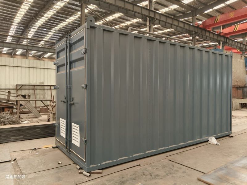
An automated hybrid system often provides the best ROI for display panel manufacturers handling mixed waste streams. These systems use lime for bulk neutralization of high-volume alkaline waste and CO₂ for final polishing. This approach minimizes scaling while keeping chemical costs manageable. For a 50 GPM system, a hybrid setup typically pays for itself within 32 months compared to a pure lime system, primarily through a 60% reduction in pipe descaling maintenance and lower sludge handling fees.
| Technology | CapEx (¥/GPM) | OpEx (¥/m³) | pH Accuracy | Scaling Risk | Sludge (kg/m³) |
|---|---|---|---|---|---|
| Lime (Manual/Basic) | ¥24,000 | ¥0.80 | ±0.5 | High | 0.4–0.6 |
| CO₂ (Injection) | ¥40,000 | ¥1.20 | ±0.1 | Low | <0.05 |
| Automated Hybrid | ¥60,000 | ¥1.50 | ±0.1 | Medium | 0.1–0.2 |
Integrated Pretreatment: Handling Co-Contaminants in Display Panel Wastewater
Effective wastewater treatment for display panel manufacturing requires addressing co-contaminants.Neutralizing pH is only one component of a compliant display panel wastewater strategy; the presence of TMAH, HF, and heavy metals necessitates integrated pretreatment. TMAH, used in the developer process, creates high Chemical Oxygen Demand (COD) and Total Dissolved Solids (TDS), often exceeding 5000 mg/L. Standard pH adjustment does not remove TMAH; it requires TMAH-specific wastewater treatment strategies involving advanced oxidation or specialized biological processes.
Similarly, etching processes generate high concentrations of fluoride from HF. To meet EPA fluoride limits of <4 mg/L, manufacturers must implement chemical precipitation using calcium chloride (CaCl₂) prior to or during the neutralization phase. This process converts soluble fluoride into insoluble calcium fluoride (CaF₂), which can then be removed using DAF systems for TSS and FOG removal in display panel wastewater. DAF technology is particularly effective here, achieving 95% efficiency in solids separation at flow rates from 4 to 300 m³/h.
For heavy metals like copper and nickel, which are prevalent in CMP and plating lines, MBR systems for heavy metal recovery and ZLD compliance provide a robust solution. MBRs combine biological treatment with membrane filtration to achieve 99%+ removal of heavy metals, ensuring the final effluent meets the strictest global standards. For more on this, engineers should consult specialized guides on heavy metal recovery in display panel wastewater and HF-specific pretreatment for display panel wastewater.
Compliance and Cost Optimization: A Step-by-Step Guide for Display Panel Manufacturers
Achieving zero-risk compliance requires a systematic engineering approach that begins with precise influent characterization. Manufacturers should follow these five steps to optimize their wastewater infrastructure for 2025 standards:
- Comprehensive Influent Mapping: Conduct 24-hour composite sampling to identify peak concentrations of TMAH, HF, and copper. Understanding the "worst-case" pH swings (e.g., pH 2 to 12) is critical for sizing dosing pumps.
- Technology Selection: Match the neutralization reagent to the discharge goal. Use CO₂ for ZLD to prevent RO membrane scaling; use lime for high-alkalinity streams where sludge disposal is already managed.
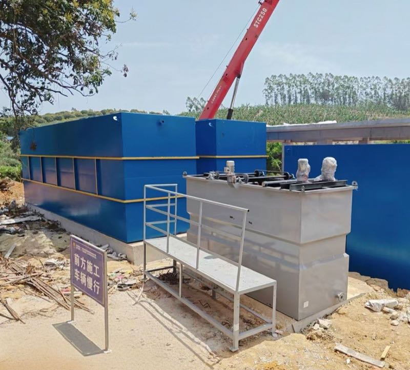
- Modular Pretreatment Design: Integrate DAF units for solids removal and MBR modules for metal recovery. This modularity allows for scaling as production capacity increases.
- Pilot Validation: Run a pilot test at 10% of full flow (e.g., 5 GPM for a 50 GPM target) to validate the PID control loops and reagent consumption rates.
- OpEx Optimization: Implement sludge reuse programs—such as using lime sludge for flue gas desulfurization (FGD)—and automate chemical dosing to reduce reagent waste by up to 20%.
| Cost Component | Estimated Range (50 GPM System) | Optimization Strategy |
|---|---|---|
| Capital Expenditure (CapEx) | ¥1.5M – ¥5.0M | Modular skid-mounted designs |
| Operating Expenditure (OpEx) | ¥0.8 – ¥2.0 per m³ | Automated PID dosing control |
| Sludge Disposal | ¥0.2 – ¥0.5 per kg | Dewatering to 30% solids |