Data Center Blowdown ZLD Cost Analysis
A data center blowdown ZLD cost analysis starts from recovery, energy, and discharge price, not from a brand name. Partial RO recovery of 75–85% usually costs less energy, at 0.8–1.5 kWh/m³, than a 99%+ crystallizer train at 5–10 kWh/m³. Payback tightens where discharge fees sit near $2.50/m³.
Data center blowdown reuse recovers 75–99% of cooling-tower purge water, depending on feed TDS and the selected train. A typical 100-MW campus uses about 2 million liters of water per day, with 25–30% leaving as blowdown. Discharge fees of $0.50–$5.00/m³ ($2.50/m³ in basins such as Arizona) set the economic boundary for RO, EDR, or ZLD. Local utility rules and EPA effluent guidelines shape permit risk.
Corporate water goals still push operators toward higher recovery. According to Microsoft (2026), FY25 was the first year replenishment exceeded withdrawals, at more than 14 million cubic meters, and the 2030 water-positive commitment remains in force. The same 2026 update says global volume matching is not a local watershed balance. Ignoring blowdown recovery raises both fee exposure and permit risk.
According to Microsoft (2026), average datacenter water use effectiveness fell from 2.3 L/kWh on early designs to 0.27 L/kWh in 2025. About 90% of the 2025 owned fleet now uses low-water or zero-water cooling. Most campuses we review still size the blowdown train on the local fee, because evaporative halls remain. Blowdown cost work stays live on that remainder, especially in hot basins.
Cooling Tower Blowdown Reuse Engineering Specs 2026
Cooling tower blowdown reuse engineering specs for 2026 still start with measured chemistry, not with a catalog recovery claim. Cooling tower blowdown water typically exhibits Total Dissolved Solids (TDS) ranging from 1,200 mg/L to 6,000 mg/L at common cycles of concentration. This concentration can spike during operational upsets or routine chemical dosing. Common contaminants include silica (50–150 mg/L), calcium (200–800 mg/L), magnesium (100–400 mg/L), and chlorides (300–1,500 mg/L).
Biological growth, with counts ranging from 104 to 106 CFU/mL, is also a prevalent issue. The potential for scaling is critical; a Langelier Saturation Index (LSI) greater than 0.5 indicates a high risk of mineral precipitation. The cycles of concentration directly influence water quality, as illustrated in the table below:
| Cycles of Concentration (CoC) | Typical TDS (mg/L) | Typical Hardness (mg/L as CaCO₃) | Typical Silica (mg/L) |
|---|---|---|---|
| 2 | 600 - 1,200 | 100 - 400 | 15 - 30 |
| 4 | 1,200 - 2,400 | 200 - 800 | 30 - 60 |
| 6 | 1,800 - 3,600 | 300 - 1,200 | 45 - 90 |
| 8 | 2,400 - 4,800 | 400 - 1,600 | 60 - 120 |
| 10 | 3,000 - 6,000 | 500 - 2,000 | 75 - 150 |
Addressing these contaminants protects downstream membranes and heat exchangers. A high-efficiency DAF system for blowdown pretreatment can remove solids before softening or RO. Most plants we size for 4–6 CoC sit in the middle of the TDS band above, not at the extremes.
According to ASHRAE Addendum i to Standard 189.1-2017, towers on makeup below 200 mg/L hardness as CaCO₃ should reach at least 5 cycles of concentration. Makeup above 200 mg/L as CaCO₃ should reach at least 3.5 cycles. The minimum is waived if discharge TDS exceeds 1500 mg (1500 ppm/L) or silica exceeds 150 mg/L as silicon dioxide. The addendum also caps recirculating water at 2050 ppm TDS, 150 ppm silica, 300 ppm chloride, and LSI +2.8, and it withholds blowdown until a listed parameter hits 90% of that cap.
Blowdown chloride in the 300–1,500 mg/L band can already meet or pass that 300 ppm recirculating cap. On jobs we review, the silica exception arrives before the cycle target when makeup silica is already high. The same addendum expects the tower water system to tolerate pH 7.0 to 9.2. Set the operating LSI alarm at greater than 0.5 even though the materials ceiling is +2.8.
High Silica Cooling Tower Blowdown RO Recovery
High silica cooling tower blowdown RO recovery usually stalls before the nameplate recovery when silica reaches 65–150 mg/L. Partial RO trains typically return 75–85% of blowdown as makeup-quality permeate when feed TDS stays below about 5,000 mg/L. Conventional brackish RO often stalls near 75–80% recovery in that silica band, so higher recovery needs softening, antiscalant control, or a brine stage (IDE Technologies, 2026). Minimal liquid discharge and crystallizer packages raise recovery to 90–99%+, but energy and solids handling rise with brine TDS.
For campus-wide planning beyond blowdown alone, compare notes with data center liquid cooling wastewater treatment specs. Most plants we size stop the RO stage once concentrate silica nears the 150 mg/L recirculating cap, then send only that brine onward.
EDR vs RO Cooling Tower Blowdown System
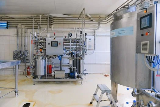
An EDR vs RO cooling tower blowdown system choice is an energy and scaling choice: RO uses 0.8–1.5 kWh/m³ up to about 5,000 mg/L TDS, while EDR uses 1.2–2.0 kWh/m³ up to 12,000 mg/L. Treatment technology selection for blowdown reuse is driven by water quality, target recovery, and unit energy cost. Each option trades recovery against CAPEX, OPEX, and scaling risk:
| Technology | Recovery Rate (%) | TDS Range (mg/L) | Energy Use (kWh/m³) | Approx. CAPEX ($/m³ capacity) | Approx. OPEX ($/m³ treated) | Scaling Risk |
|---|---|---|---|---|---|---|
| Reverse Osmosis (RO) | 75 – 85 | Up to 5,000 (without advanced pretreatment) | 0.8 – 1.5 | 1,000 – 3,000 | 0.30 – 0.70 | Moderate to High (silica, calcium, magnesium) |
| Electrodialysis Reversal (EDR) | 90 – 95 | Up to 12,000 | 1.2 – 2.0 | 1,500 – 3,500 | 0.50 – 1.20 | High (requires frequent cleaning for scaling) |
| Membrane Distillation (MD) | 95 – 99 | > 10,000 | 3.0 – 3.5 | 10,000 – 20,000 | 1.00 – 2.50 | Low (less sensitive to scaling, but fouling can occur) |
| Crystallizers (Evaporation/Crystallization) | 99+ (ZLD) | > 30,000 | 5 – 10 | 15,000 – 30,000+ | 2.00 – 5.00+ | Minimal (produces solid waste) |
Reverse osmosis remains the default when TDS stays under 5,000 mg/L and silica is controlled. Electrodialysis reversal fits higher TDS and a 90–95% recovery target, but scaling still demands frequent cleaning. Membrane distillation at 3.0–3.5 kWh/m³ and crystallizers at 5–10 kWh/m³ belong on brine, not on raw blowdown. For high recovery, pair industrial RO systems for blowdown water recovery with a sedimentation tank ahead of the membranes.
On the trains we commission, chloride is rarely the first limit. Silica and calcium carbonate set the cleaning interval. EDR can post a higher recovery number and still lose availability if the reversal cycle is late. Pick the train whose scaling column you can live with at the design CoC, not at a diluted sample.
What pretreatment stops scale before RO or EDR?
Pretreatment stops scale before RO or EDR when solids, hardness, and silica are cut before the membrane. A plant that doses antiscalant without softening still scales. Most trains we commission put clarification ahead of ion exchange, not after the RO skid.
- Dissolved Air Flotation (DAF): A high-efficiency DAF system can remove 90–95% of suspended solids and emulsified oils and greases (FOG).
- Softening (Lime or Ion Exchange): Reducing water hardness by 80–90% is critical for preventing scaling in RO and EDR systems.
- Antiscalants and Biocides: The precise dosing of antiscalants inhibits crystal formation and extends membrane life by 20–30%. An automatic chemical dosing system ensures accurate and consistent application.
For blowdown water with TDS exceeding 4,000 mg/L, a typical pretreatment process flow might involve chemical conditioning, followed by clarification or sedimentation, and then multi-media filtration. Skip that step and silica or calcium carbonate will force early cleanings within weeks, not months.
ZLD vs MLD Data Center Blowdown Payback
ZLD vs MLD data center blowdown payback is set by discharge fee, makeup price, and whether brine can leave the site. Zero liquid discharge offers the highest recovery and the tightest compliance path, but it raises CAPEX and thermal OPEX. Long-term savings grow fastest where discharge exceeds about $2.00/m³ or sewer capacity is capped. This data center blowdown ZLD cost analysis uses that fee gate before any crystallizer is specified.
Five line items move payback more than the recovery percentage does: discharge fee, makeup price, power, solids haul-off, and cleaning. Power at 0.8–1.5 kWh/m³ for RO versus 5–10 kWh/m³ for a crystallizer is the widest gap. Solids haul-off grows only when recovery pushes brine toward a crystallizer. Most plants we price see cleaning frequency, not the skid quote, decide whether MLD stays inside a 3–7 year payback.
| System Type | Approx. CAPEX ($/m³ treated water) | Approx. OPEX ($/m³ treated water) | Typical Payback Period (Years) | Key Benefit |
|---|---|---|---|---|
| Partial Recovery (75-85%) | 1 – 4 | 0.50 – 1.50 | 2 – 5 | Reduced freshwater demand, lower discharge costs |
| MLD (90-95% Recovery) | 3 – 8 | 0.80 – 2.00 | 3 – 7 | Significant water savings, meets stricter discharge limits |
| ZLD (99%+ Recovery) | 5 – 15 | 1.50 – 4.00 | 4 – 8 | Maximized water reuse, compliance with water-positive goals and stringent regulations |
When should a campus skip thermal ZLD?
A campus should skip thermal ZLD when brine has a permitted sewer path and the discharge fee stays near the low end of $0.50–$5.00/m³. Crystallizers at 15,000 – 30,000+ $/m³ capacity and 5–10 kWh/m³ rarely beat partial RO in that case. Most plants we size for open sewers stop at 75–85% recovery. Move to ZLD when the fee approaches $2.50/m³ or the permit blocks brine.
Arizona Data Center Blowdown Discharge Fee Savings
Arizona data center blowdown discharge fee savings are large only when the fee hits nearly all of the avoided discharge. Consider a 50-MW data center operating in Arizona with an average discharge fee of $2.50/m³. Implementing a ZLD system could recover 95% of its daily water usage. If the facility uses 1 million liters/day of makeup water, saving 950,000 liters daily at a discharge cost of $2.50/m³ translates to an annual saving of over $830,000 in discharge fees alone.
According to Microsoft (2026), direct evaporative assist uses water only when outside air exceeds 85°F (29.4°C), and in Phoenix that share can reach 40% of the year. Those Phoenix datacenters improved WUE by 23% year over year in FY25. The efficiency gain shrinks blowdown volume. It does not erase a $2.50/m³ fee on the purge that remains.
Line-item budgets for a cooling tower blowdown recovery system capex opex cost data center belong on the dedicated cost page, not in this process brief. For recovery layout detail, read the detailed engineering specs for cooling tower blowdown recycling.
Do High-Purity Water Systems Serve Data Center Cooling?
High-purity water systems for data center cooling are usually limited to closed-loop or liquid-cooled loops, not open cooling-tower makeup. Tower makeup after blowdown treatment typically targets low hardness and controlled silica, not semiconductor-grade UPW resistivity. If your campus also runs chillers or adiabatic pads, specify the loop quality separately from CTBD permeate so you do not overspend on polishing.
Where biological load or organics appear in combined streams, an MBR Membrane Bioreactor Wastewater Treatment System can stabilize pretreatment before RO. Keep UPW piping standards and long-term fab cost data on the semiconductor side of the campus, not in the tower reuse train. Closed-loop liquid cooling is a different wastewater stream; see Data Center Liquid Cooling Wastewater: 2026 Treatment Specs, 40% Water.
How to Select the Right Blowdown Water Reuse System for Your Data Center
Blowdown water reuse system selection for a data center should follow a fixed checklist before any CAPEX quote. Work the steps in order:
- Water Quality Analysis: Conduct comprehensive laboratory testing of your cooling tower blowdown water for TDS, hardness, silica, chloride, and LSI at current CoC.
- Define Recovery Goals: Determine your target water recovery rate (75–85%, 90–95%, or 99%+) against discharge and makeup prices.
- Technology Comparison: Evaluate treatment technologies using the recovery, energy, and scaling columns above.
- Pilot Testing: Before full-scale deployment, conduct a pilot test of the selected system(s) on real CTBD for at least several weeks.
- Brine path: Confirm sewer, haul-away, or crystallizer solids handling before locking ZLD.
- Controls: Specify continuous conductivity, pH, and antiscalant dose control with documented setpoints.
- Vendor scope: Require guaranteed recovery at the design silica and hardness envelope, not only at diluted pilot water.
Operators can review Data Center Cooling Water Reclaim System for a parallel reclaim layout. A separate layout with the recovery notes is Cooling Tower Blowdown Recycling: 2026 Engineering Specs, 99% Recovery. On bids we review, the failure mode is a promise written on diluted pilot water rather than on the design silica.
Who This Is For / Next Step
This guide is for plant engineers, EPC teams, and procurement managers sizing evaporative-cooled campuses that already measure blowdown chemistry. Teams running only closed-loop liquid cooling with no tower purge should look at liquid-cooling wastewater pages instead. According to Microsoft (2026), a 2024 datacenter design consumes zero water for cooling during operations, so those halls have no blowdown to recover. If you have recent CTBD lab data and a target recovery band, request a blowdown reuse equipment quote with your TDS, silica, and daily flow.
Frequently Asked Questions
What is the typical TDS range of cooling tower blowdown water?
Cooling tower blowdown water typically has a TDS range of 1,200 mg/L to 6,000 mg/L at common operating cycles. Values rise with higher cycles of concentration and can spike during chemical dosing or upsets. Hardness, silica, and chloride usually climb with TDS, so design on recent lab data rather than nameplate makeup quality alone. At 4–6 CoC, most plants we size sit between the 1,200 mg/L and 3,600 mg/L rows, not at 10 cycles.
What percentage of makeup water can be recovered from cooling tower blowdown?
Recovery rates range from 75% with basic RO systems to over 99% with membrane distillation or evaporation/crystallization technologies. The achievable band depends on feed TDS, silica, and whether brine can be discharged or must become solids. Most campuses start at 75–85% RO recovery, then add MLD or ZLD only when discharge limits force it. A 90–99%+ target is a solids-handling decision, not a default membrane setting.
What are the primary contaminants in blowdown water that affect treatment systems?
The primary contaminants are dissolved solids (TDS), hardness-forming minerals, silica, and biological growth. Calcium at 200–800 mg/L and magnesium at 100–400 mg/L drive carbonate scale when LSI exceeds 0.5. Silica at 50–150 mg/L often caps RO recovery before chloride at 300–1,500 mg/L does. Counts of 104 to 106 CFU/mL are why biocide control sits with softening, not after the membranes.
How does the Langelier Saturation Index (LSI) impact blowdown water treatment?
An LSI greater than 0.5 indicates a propensity for calcium carbonate scaling on heat-transfer and membrane surfaces. Operators usually correct LSI with acid, softening, or antiscalant before raising recovery. Ignoring a positive LSI shortens membrane life even when bulk TDS looks acceptable on paper. ASHRAE Addendum i to Standard 189.1-2017 allows recirculating LSI up to +2.8 as a materials ceiling, which is not the same as the 0.5 operating alarm.
What is the energy consumption difference between RO and Membrane Distillation for blowdown reuse?
RO typically consumes 0.8–1.5 kWh/m³ on blowdown within its normal TDS window, whereas Membrane Distillation ranges from 3.0–3.5 kWh/m³. Crystallizers used for 99%+ ZLD sit higher still, at about 5–10 kWh/m³. EDR usually falls between those bands, at 1.2–2.0 kWh/m³, with recovery of 90–95%. Choose MD or thermal steps when brine TDS exceeds what RO can reject, not as a default first stage.