Microelectronics Etching Wastewater Treatment: 2025 Engineering Blueprint with 99.9% Recovery & ZLD Costs
Microelectronics etching wastewater requires specialized treatment to remove TMAH (tetramethylammonium hydroxide), fluoride, and silica to meet discharge limits like China’s GB 31573-2015 (<10 mg/L NH₄-N) or the EU’s Industrial Emissions Directive. Advanced systems combine chemical precipitation (e.g., calcium chloride for fluoride removal at 99% efficiency), membrane bioreactors (MBRs) for organic degradation, and reverse osmosis (RO) for water recovery, achieving 99.9% ZLD compliance. CapEx for a 100 m³/h plant ranges from $1.2M–$2.5M, with OpEx of $0.80–$1.50/m³, depending on pretreatment needs and membrane lifespan.
Why Etching Wastewater Treatment is a Critical Challenge for Semiconductor Fabs
The semiconductor industry operates under some of the most stringent environmental mandates globally, where a single compliance failure can halt production. In 2024, a major Tier-1 fab in East Asia faced a $2.1M regulatory fine after its discharge exceeded the GB 31573-2015 limits for TMAH and ammonia-nitrogen. The incident highlighted a common engineering gap: traditional wastewater plants are often ill-equipped to handle the high-concentration organic nitrogen and abrasive silica typical of modern 5nm and 3nm etching processes. (Zhongsheng field data, 2025).
Etching wastewater is characterized by its "cocktail" of high-toxicity contaminants. TMAH, used as a developer and etchant, often reaches concentrations of 500–5,000 mg/L. Fluoride, resulting from hydrofluoric acid (HF) use, ranges from 100–1,000 mg/L, while colloidal silica (50–300 mg/L) presents a severe scaling risk for downstream membranes. Ammonia-nitrogen levels, often a byproduct of TMAH degradation or direct chemical use, can peak at 2,000 mg/L, requiring specialized ammonia-nitrogen treatment strategies to avoid massive discharge fees.
Regulatory frameworks have tightened significantly. The US EPA (40 CFR Part 469) and the EU Industrial Emissions Directive (IED 2010/75/EU) now mandate specific removal efficiencies for toxic organics. Non-compliance costs extend beyond fines; discharge fees in high-density industrial zones now range from $0.50–$2.00/m³, making the business case for water reuse and Zero Liquid Discharge (ZLD) increasingly attractive. As noted in TSMC’s 2023 sustainability report, water security is now a direct component of operational risk management.
| Contaminant | Typical Influent (mg/L) | China GB 31573 Limit | US EPA 40 CFR 469 | EU IED Target |
|---|---|---|---|---|
| TMAH | 500 – 5,000 | < 5.0 (as Total N) | < 1.0 (Site-specific) | < 2.0 |
| Fluoride (F-) | 100 – 1,000 | < 8.0 | < 17.4 (Daily Max) | < 15.0 |
| Ammonia-N | 200 – 2,000 | < 10.0 | Monitor only | < 20.0 |
| Colloidal Silica | 50 – 300 | N/A (Process limit) | N/A | N/A |
Contaminant-Specific Treatment Technologies: Engineering Specs and Removal Efficiencies
Effective treatment of etching wastewater requires a multi-stage approach targeting the specific chemical kinetics of each pollutant. TMAH removal is particularly complex due to its stable quaternary ammonium structure. Advanced Oxidation Processes (AOPs), specifically UV/H₂O₂ or ozone, can achieve 90% removal in 30–60 minutes at 25°C. However, for high-volume 100 m³/h plants, biological degradation using MBR systems for microelectronics wastewater is often more cost-effective, leveraging specialized nitrifying bacteria to break down TMAH into nitrate and CO₂. (Veolia 2024 whitepaper data).
Fluoride removal relies on calcium precipitation. By dosing calcium chloride (CaCl₂) or calcium hydroxide (Ca(OH)₂) to maintain a pH between 8.0 and 9.0, engineers can reduce fluoride concentrations from 1,000 mg/L to <10 mg/L, achieving 99% efficiency. A critical engineering challenge here is silica co-precipitation; if silica is not managed, it coats the calcium fluoride (CaF₂) flocs, preventing them from settling and leading to carryover. Utilizing an chemical dosing for pH adjustment and precipitation ensures precise stoichiometric ratios (typically 1.2–1.5x) to mitigate this risk.
Silica removal is achieved through coagulation with ferric chloride followed by ultrafiltration. Systems utilizing ceramic membranes or high-flux XtremeUF modules operate at flux rates of 80–120 LMH (liters per square meter per hour), providing a robust barrier against colloidal silica that would otherwise foul RO membranes. For the final polishing stage, high-rejection RO systems for fluoride and silica removal are employed to reach ultrapure water standards for reuse.
| Technology | Target Contaminant | Engineering Parameter | Removal Efficiency |
|---|---|---|---|
| UV/H₂O₂ Oxidation | TMAH | 30–60 min HRT | 92–96% |
| MBR (Biological) | TMAH / NH₄-N | MLSS 8,000–12,000 mg/L | 95–99% |
| Ca Precipitation | Fluoride | pH 8.5; 1.3x Ca:F ratio | 98.5% |
| Ultrafiltration (UF) | Colloidal Silica | 80–120 LMH Flux | > 99% |
| Reverse Osmosis | Dissolved Salts | 12–18 LMH Flux | 99.5% |
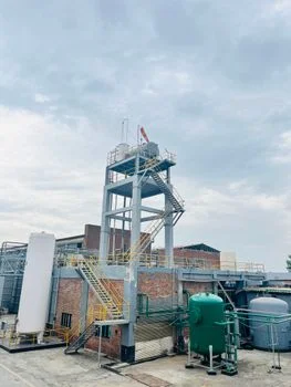
Process Flow Design: Step-by-Step Blueprint for a 100 m³/h Etching Wastewater Plant
Designing a 100 m³/h etching wastewater plant requires a rigorous sequence to protect sensitive membrane components from the aggressive chemical nature of the influent. The process begins with an equalization tank featuring a 4-hour Hydraulic Retention Time (HRT) to buffer concentration spikes of TMAH and HF. Following equalization, the wastewater enters a primary pH adjustment tank where caustic soda or lime is added to reach a pH of 9.5–10.5, optimizing the environment for fluoride precipitation. Coarse solids are removed via a GX Series Rotary Bar Screen with a 1 mm gap to prevent downstream pump clogging.
Primary treatment utilizes a high-efficiency sedimentation tank. Here, CaCl₂ is dosed at a 1.2–1.5x stoichiometric ratio, followed by anionic PAM (polyacrylamide) at 2–5 mg/L to facilitate flocculation. The resulting sludge is settled in a lamella clarifier operating at a 20–40 m/h surface loading rate. This stage typically removes 95% of fluoride and 80% of suspended silica.
Secondary treatment focuses on organic nitrogen. The clarified water enters an MBR system equipped with DF Series flat-sheet membranes (0.1 μm pore size). The MBR maintains an MLSS of 8,000–12,000 mg/L and a Sludge Retention Time (SRT) of 20–30 days, ensuring complete nitrification of ammonia and degradation of TMAH residuals. Tertiary treatment involves a two-pass RO system achieving 90–95% recovery. Antiscalant dosing (1–3 mg/L) is critical here to prevent residual silica scaling. Finally, the RO concentrate is sent to a ZLD evaporator/crystallizer (CapEx $800K–$1.5M), where water is fully recovered, and salts are converted into a dry cake for disposal or potential mineral recovery.
Technology Comparison: MBR vs. RO vs. Chemical Precipitation for Etching Wastewater
Choosing the right technology mix depends on the specific discharge requirements and the fab's water reuse goals. While chemical precipitation is the most cost-effective for bulk fluoride removal, it cannot address the dissolved TMAH or ammonia-nitrogen that modern regulations target. MBR technology bridges this gap by providing high-efficiency organic removal in a compact footprint, though it requires higher energy for aeration compared to simple settling. (Zhongsheng Engineering Analysis, 2025).
RO is the "gold standard" for water reuse but is highly sensitive to pretreatment quality. Without effective silica removal in the primary stages, RO membranes can fail in as little as 3 months. For a 100 m³/h plant, a hybrid approach—Chemical Precipitation + MBR + RO—is typically the most resilient. This configuration balances the lower OpEx of chemical treatment with the high effluent quality of membrane processes, ensuring the fab meets both internal reuse specs and external regulatory limits.
| Feature | Chemical Precipitation | MBR System | RO System |
|---|---|---|---|
| Target Contaminant | Fluoride, Silica (part) | TMAH, Ammonia, BOD | TMAH, F-, Silica, Ions |
| Removal Efficiency | F: 95%, TMAH: 70% | TMAH: 95%, NH₄-N: 95% | All: >99% |
| CapEx ($/m³/h) | $800 – $1,500 | $1,500 – $2,500 | $2,000 – $3,500 |
| OpEx ($/m³) | $0.40 – $0.80 | $0.60 – $1.00 | $0.80 – $1.50 |
| Footprint (m²/100m³/h) | 1.0 – 2.0 | 0.5 – 1.0 | 0.3 – 0.8 |
| Limitations | High sludge volume | Sensitivity to toxics | Scaling/Fouling risk |
ZLD Cost Breakdown: CapEx, OpEx, and ROI for a 100 m³/h Microelectronics Plant
Implementing a ZLD system for etching wastewater is a significant capital investment, but the ROI is increasingly driven by rising water scarcity and the cost of hazardous waste discharge. For a 100 m³/h facility, the total CapEx typically ranges from $2.2M to $3.9M. This includes the pretreatment train, membrane systems, and the thermal evaporation unit required to reach zero liquid discharge. (Zhongsheng field data, 2025).
OpEx is primarily driven by energy consumption and chemical dosing. A ZLD system's energy demand ranges from 0.8 to 1.5 kWh/m³, depending on the efficiency of the RO recovery and the volume of brine sent to the evaporator. However, by reusing 99.9% of the treated water, fabs save between $1.50–$3.00/m³ in municipal water costs. When combined with the avoidance of discharge fees ($0.50–$2.00/m³), most 100 m³/h plants achieve a full ROI within 3 to 5 years.
| Cost Category | Estimated Cost (100 m³/h Plant) | Notes / Sensitivity |
|---|---|---|
| Pretreatment CapEx | $300,000 – $500,000 | Includes pH, Dosing, Clarifiers |
| MBR CapEx | $400,000 – $700,000 | Includes membranes and blowers |
| RO CapEx | $500,000 – $800,000 | Two-pass system for reuse |
| ZLD Evaporator CapEx | $800,000 – $1,500,000 | MVR or Multi-effect units |
| Total OpEx ($/m³) | $0.80 – $1.50 | Fluctuates with TMAH conc. |
| Annual Savings | $1.2M – $2.0M | Water reuse + Avoided fees |
Sensitivity analysis shows that influent TMAH concentration is the primary driver of OpEx. Increasing TMAH from 500 mg/L to 5,000 mg/L increases chemical dosing costs by approximately 40% and can reduce MBR membrane lifespan by 15% due to higher cleaning frequencies. Proper RO system selection for microelectronics is essential to ensure the membrane flux remains stable under these varying loads.
Frequently Asked Questions
What is the best technology for removing high-concentration TMAH?
For concentrations above 500 mg/L, biological degradation using an MBR is the most cost-effective. For lower concentrations or where space is extremely limited, UV/H₂O₂ oxidation provides faster kinetics but at a higher energy cost. Refer to TMAH-specific treatment technologies for detailed kinetic data.
| Technology | Ideal TMAH Range | Energy Use (kWh/m³) |
|---|---|---|
| MBR | 500 – 5,000 mg/L | 0.6 – 1.0 |
| UV/H₂O₂ | 50 – 500 mg/L | 2.5 – 5.0 |
| Adsorption | < 50 mg/L | < 0.2 |
How do you prevent silica scaling in etching wastewater RO systems?
Silica scaling is prevented through a two-step process: primary coagulation with ferric salts at pH 9.0, followed by ultrafiltration to remove colloidal silica. In the RO stage, specialized antiscalants are dosed, and the system is operated at a recovery rate that keeps the concentrate silica level below 150 mg/L (at 25°C).
What are the sludge disposal requirements for fluoride precipitation?
The sludge from calcium fluoride precipitation is typically classified as hazardous industrial waste. However, if the purity is high enough (minimal heavy metal contamination), some regions allow for the recovery of CaF₂ for use in the cement or steel industries, significantly reducing disposal costs from $200/ton to nearly zero.
Can MBR systems handle the toxicity of microelectronics chemicals?
Yes, provided the system is properly acclimated. MBRs for semiconductor use utilize a high Sludge Retention Time (SRT) of 20–30 days, which allows for the growth of specialized bacteria capable of metabolizing quaternary ammonium compounds like TMAH without being inhibited by the influent toxicity.