Why PCB Wastewater Discharge Standards Are Non-Negotiable in 2025
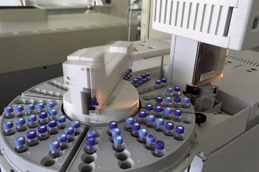
PCB wastewater discharge standards require effluent concentrations below 0.5 ppb (EPA 40 CFR 761), with stricter limits in the EU (0.1 ppb for surface water) and China (0.003 mg/L for industrial discharge). Treatment trains combining activated carbon adsorption (99.9% removal at 100 ppb influent) and membrane filtration (NF/RO) are industry-standard for compliance. Sampling must follow EPA 608.3 protocols: pH 5.0–9.0, refrigeration ≤6°C, and extraction within 7 days to avoid volatilization losses. Failure to meet these metrics results in severe regulatory action, as evidenced by a $1.2M EPA fine levied against a Midwest transformer recycling plant in 2024 after effluent samples exceeded the 0.5 ppb threshold during a routine inspection.
Polychlorinated biphenyls (PCBs) represent a unique challenge for EHS managers due to their extreme chemical stability and high potential for bioaccumulation. According to EPA 2023 data, a concentration of just 1 ppb in water can lead to concentrations exceeding 10,000 ppb in aquatic tissue, triggering IARC Group 1 carcinogenicity classifications. These risks have forced a shift in regulatory triggers: any remediation waste containing PCB concentrations >50 ppm necessitates disposal in a TSCA-approved chemical waste landfill, while concentrations between 1 and 50 ppm are restricted to specific industrial landfills under 9VAC20-81-630 guidelines.
The industry currently faces a "compliance paradox." While detection technologies like EPA Method 1668C can now identify PCB congeners at levels as low as 0.01 ppb, regulatory bodies are tightening limits in response. The EU is currently proposing a reduction of the surface water standard to 0.05 ppb by 2026. For plant operators, this means a treatment system designed for 2020 standards may be obsolete by 2027, making future-proof engineering and high-efficiency removal technologies essential for long-term operational viability.
Global PCB Wastewater Discharge Limits: EPA vs. EU vs. China GB vs. Japan
The United States Environmental Protection Agency (EPA) enforces a strict 0.5 ppb discharge limit for all PCB remediation waste under 40 CFR 761, excluding only "totally enclosed" systems such as transformers still in active service. This standard serves as the baseline for many global regulations, yet regional variations exist based on the sensitivity of local watersheds and the maturity of industrial infrastructure. For instance, the EU Water Framework Directive (2000/60/EC) sets a more aggressive target of 0.1 ppb for surface waters, reflecting a priority on protecting complex aquatic ecosystems from persistent organic pollutants (POPs).
| Region / Regulation | Industrial Discharge Limit | Surface/Drinking Water Limit | Sampling Frequency | Primary Enforcement Agency |
|---|---|---|---|---|
| USA (EPA 40 CFR 761) | 0.5 ppb (µg/L) | 0.0005 ppb (MCLG) | Quarterly / Event-based | US EPA / State DEP |
| European Union (2008/105/EC) | 0.1 ppb (µg/L) | 0.01 ppb (Proposed 2026) | Monthly | EEA / National Agencies |
| China (GB 8978-1996) | 0.003 mg/L (3 ppb) | 0.00002 mg/L (0.02 ppb) | Weekly for Class I | MEE (Ministry of Ecology) |
| Japan (Water Pollution Act) | 0.0005 mg/L (0.5 ppb) | Not Detectable (ND) | Monthly (>1kg handling) | Ministry of the Environment |
In China, the GB 8978-1996 standard mandates a limit of 0.003 mg/L (3 ppb) for industrial discharge, which aligns with broader global wastewater discharge standards for electronics manufacturing but often lacks the specific congener-based sampling protocols found in Western regulations. Consequently, many multinational firms operating in China adopt EPA 608.3 as a best practice to ensure internal ESG goals are met. Japan’s regulations mirror the US limit of 0.5 ppb but impose stricter administrative burdens, requiring monthly sampling for any facility handling more than 1 kg of PCBs per year. Penalties for violations across these jurisdictions range from administrative fines to criminal prosecution and immediate facility shutdowns.
PCB Treatment Technologies: Engineering Specs, Removal Rates & Cost Breakdown
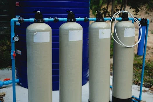
Selecting a treatment technology requires balancing influent PCB concentration against the required effluent limit. Granular Activated Carbon (GAC) remains the most common primary treatment due to its affinity for hydrophobic organic molecules. According to EPA 2024 benchmarks, GAC achieves a 99.9% removal rate when influent concentrations are near 100 ppb. However, GAC performance is highly sensitive to Empty Bed Contact Time (EBCT); engineers typically design for 10–20 minutes of contact to ensure breakthrough does not occur prematurely. When influent levels exceed 1,000 ppb, membrane systems or chemical oxidation are required to prevent rapid media exhaustion.
| Technology | Removal Efficiency | Influent Range | CAPEX ($/m³/day) | OPEX ($/m³) | Best Use Case |
|---|---|---|---|---|---|
| GAC Adsorption | 99.9% | 10–1,000 ppb | $500 – $1,200 | $0.50 – $1.00 | Bulk removal / Polishing |
| Nanofiltration (NF) | 99.95% | <500 ppb | $1,500 – $2,500 | $1.20 – $1.80 | Strict <0.1 ppb limits |
| Reverse Osmosis (RO) | 99.99% | <2,000 ppb | $2,000 – $3,500 | $1.50 – $2.50 | Zero-risk compliance |
| UV/H₂O₂ Oxidation | 95–99% | 100–10,000 ppb | $3,000 – $5,000 | $2.00 – $4.00 | High-strength waste |
| MBR (Biological) | 85–95% | <10 ppb | $1,200 – $2,000 | $0.80 – $1.20 | Pre-treated streams |
Membrane technologies offer the highest level of security for meeting ultra-low discharge limits. Implementing RO membranes for PCB polishing to 0.5 ppb allows for the removal of not just PCBs, but also dissolved solids and heavy metals. However, RO requires significant pre-treatment; Total Suspended Solids (TSS) must be below 50 mg/L and oil/grease below 10 mg/L to prevent irreversible fouling. For lower concentration streams, MBR systems for low-PCB wastewater (<10 ppb) can be effective, utilizing specialized bacteria like Dehalococcoides, though these biological processes require long Hydraulic Retention Times (HRT) of 24–48 hours and co-metabolism with biphenyl to remain active.
Designing a PCB Wastewater Treatment Train: Step-by-Step Engineering Blueprint
A robust PCB treatment train must account for the chemical's tendency to adsorb to solids and oils. The design begins with Step 1: Influent Characterization. Following EPA 608.3 protocols, samples must be collected in amber glass bottles to prevent UV degradation and plastic adsorption. If oil and grease exceed 10 mg/L, they will coat GAC media or foul membranes, rendering the entire system ineffective. Step 2: Pre-treatment addresses this by utilizing DAF systems for PCB wastewater pre-treatment, which effectively removes emulsified oils and PCB-laden suspended solids.
Step 3: Primary Treatment typically involves GAC adsorption. For a flow of 100 m³/day at 500 ppb, a dual-vessel lead-lag configuration is recommended to allow for media replacement without downtime. Step 4: Secondary Treatment (Polishing) uses NF or RO to reach the final <0.5 ppb or <0.1 ppb target. This stage must include Clean-In-Place (CIP) protocols using citric acid or NaOH to maintain transmembrane pressure (TMP) within the 15–40 bar range for RO systems.
The most overlooked aspect of design is Step 5: Sludge Management. PCBs are not destroyed in physical separation; they are concentrated. Sludge with >50 ppm PCB is classified as TSCA remediation waste and must be dewatered using a high-pressure plate and frame filter press before being transported to a hazardous waste landfill. Finally, Step 6: Validation requires continuous monitoring. While lab results take days, online TOC or GC-MS analyzers can provide early warning of breakthrough, ensuring that the facility never exceeds its discharge permit.
This blueprint is particularly critical when managing wastewater treatment for PCB manufacturing byproducts, where complex chemistries and varying flow rates can destabilize simpler treatment configurations.
Compliance Decision Framework: How to Choose the Right PCB Treatment Strategy
The choice of a treatment strategy is dictated by the intersection of influent load, discharge stringency, and available budget. A facility in a region with a 0.5 ppb limit and low influent concentrations may find a GAC-only system sufficient, whereas a plant in the EU facing a 0.05 ppb limit will almost certainly require membrane polishing. The following matrix provides a technical starting point for technology selection based on Zhongsheng field data (2025).
| Scenario | Influent PCB | Flow Rate | Target Limit | Recommended Train | Est. CAPEX |
|---|---|---|---|---|---|
| Small Lab / Site | <10 ppb | <50 m³/day | 0.5 ppb | Dual-Stage GAC | $50K – $100K |
| Electronics Plant | 10–500 ppb | 100–500 m³/day | 0.1 ppb | DAF + GAC + NF | $250K – $600K |
| Transformer Recycle | >1,000 ppb | >500 m³/day | 0.5 ppb | DAF + GAC + RO | $1M – $2.5M |
| Chemical Remediation | >5,000 ppb | Variable | 0.5 ppb | Oxidation + GAC + RO | $2M+ |
To optimize costs, engineers should employ a "bulk-then-polish" approach. Using GAC for the bulk of PCB removal (reducing 500 ppb to 10 ppb) is significantly cheaper than using RO for the entire concentration range. regenerating GAC off-site can reduce OPEX by up to 30% compared to virgin carbon replacement. In high-flow scenarios, reusing RO permeate for non-potable applications like cooling tower makeup can provide a secondary ROI by reducing raw water procurement costs.
Case Study: PCB Wastewater Treatment for a Transformer Recycling Plant (0.5 ppb Compliance)
A transformer recycling facility in the US Midwest required a system to treat 1,200 m³/day of rinse water and floor washings. The influent was characterized by high variability, with PCB concentrations averaging 2,000 ppb and oil/grease levels reaching 45 mg/L. The facility was under a consent decree to meet the EPA 0.5 ppb limit or face daily fines. Zhongsheng engineers designed a treatment train consisting of coarse screening, DAF for oil removal, three-stage GAC adsorption, and a final RO polishing unit.
During the first six months of operation, the DAF unit removed 85% of the oil and grease, which was critical for protecting the GAC media. The GAC stage achieved a 99.5% removal rate, bringing the PCB concentration down to approximately 10 ppb. The final RO stage consistently produced effluent at 0.4 ppb, comfortably below the 0.5 ppb regulatory ceiling. Total capital expenditure was $2.1M ($1,750 per m³/day of capacity), with an operational cost of $1.80/m³.
Key lessons from this installation included the necessity of pH adjustment; by maintaining the influent to the RO at pH 6.5, the plant avoided calcium carbonate scaling, extending membrane life by 40%. Additionally, the implementation of an online PCB analyzer reduced the frequency of expensive EPA 608.3 lab tests by 60%, as the plant could prove continuous compliance through surrogate monitoring.
Frequently Asked Questions
Q: What is the EPA’s PCB wastewater discharge limit?
A: The EPA requires PCB concentrations below 0.5 ppb in wastewater under 40 CFR 761. This applies to all PCB remediation waste, including transformer fluids and contaminated rinse water. Sampling must follow EPA 608.3 protocols: pH 5.0–9.0, refrigeration ≤6°C, and extraction within 7 days.
Q: How do I sample PCB wastewater for compliance testing?
A: Use EPA Method 608.3: (1) Collect samples in amber glass bottles; (2) Adjust pH to 5.0–9.0 with NaOH or H₂SO₄; (3) Refrigerate at ≤6°C and protect from light; (4) Extract within 7 days. Avoid plastic containers, as PCBs readily adsorb to polyethylene surfaces.
Q: What’s the best treatment technology for PCB <0.1 ppb?
A: A two-stage system is best: (1) Granular activated carbon (GAC) for bulk removal (99.9% at 100 ppb influent); (2) Nanofiltration (NF) or reverse osmosis (RO) for polishing to <0.1 ppb. Effective pre-treatment (DAF for oil/grease) is critical to prevent fouling of these stages.
Q: Can biological treatment remove PCBs from wastewater?
A: Yes, but primarily for low concentrations (<10 ppb). Specialized bacteria like Dehalococcoides require anaerobic conditions and long HRT (24–48 hours). Biological treatment is rarely used alone due to slow kinetics and the risk of incomplete degradation (EPA 2024).
Q: How much does PCB wastewater treatment cost?
A: Costs vary by concentration and flow: (1) GAC-only systems cost $0.50–$1.00/m³; (2) GAC + NF systems cost $1.00–$2.00/m³; (3) Systems using oxidation and RO cost $2.00–$4.00/m³. Capital costs range from $50K for small units to over $3M for large-scale industrial plants.