Monocrystalline Silicon Wastewater Treatment: 2025 Hybrid ZLD System Design with 99.8% Recovery & Cost Breakdown
Monocrystalline silicon wastewater treatment requires a hybrid zero liquid discharge (ZLD) system to achieve 99.8% recovery and comply with China GB 8978-1996 and EPA 40 CFR Part 469 standards. Key contaminants—hydrofluoric acid (HF), nitric acid (HNO3), silicon particles, and phosphorus—demand a multi-stage process: dissolved air flotation (DAF) for TSS removal (95-98% efficiency), reverse osmosis (RO) for desalination (90-95% recovery), and mechanical vapor recompression (MVR) for brine concentration. A 2025 case study in Jiangsu, China, demonstrated a 30% reduction in OPEX using this hybrid approach, with payback in 2.5 years. The integration of these technologies specifically addresses the volatility of hydrofluoric acid and the abrasive nature of silicon fines, which can otherwise lead to rapid equipment degradation in less sophisticated treatment setups. By utilizing a closed-loop design, manufacturers can effectively insulate themselves from the volatility of local water utility pricing and increasingly stringent environmental discharge levies.
Why Monocrystalline Silicon Wastewater Treatment is a Regulatory and Operational Challenge
Saw damage removal and texturing processes in monocrystalline silicon production generate significant volumes of complex wastewater, typically ranging from 50 to 150 m³/day for every 100 MW of production capacity. This effluent is characterized by high concentrations of hydrofluoric acid (HF) and nitric acid (HNO3), alongside suspended silicon fines and phosphorus from doping stages. Unlike polycrystalline processes, monocrystalline texturing often utilizes alkaline solutions (NaOH/KOH), resulting in a waste stream with high pH and specific chemical oxygen demand (COD) profiles that can destabilize standard treatment plants if not properly balanced.
Regulatory frameworks have tightened significantly as of 2025. China GB 8978-1996 mandates a fluoride limit of 10 mg/L and a pH range of 6-9 for Class I discharge. Similarly, the EPA 40 CFR Part 469 standards for semiconductor and electronic component manufacturing set strict daily maximums for fluoride and total suspended solids (TSS). Failure to meet these limits carries heavy financial and operational risks. For example, a 2024 audit of a Jiangsu solar cell plant revealed 12 violations for fluoride exceedances, resulting in $450,000 in fines and a mandatory 3-week production halt to overhaul their filtration infrastructure. Furthermore, the transition from multi-crystalline to monocrystalline technology has shifted the chemical profile of the wastewater toward more alkaline-dominant streams. This shift requires precise pH neutralization before the biological or physical stages to prevent "shocking" the system, which can lead to costly downtime and biological mass death in mixed-use treatment facilities.
Beyond compliance, operational efficiency is hindered by the physical nature of silicon particles. These ultra-fine solids are highly abrasive and prone to scaling. Industry benchmarks indicate that untreated silicon particles increase maintenance costs for downstream pumps and membranes by 20-30% due to premature mechanical seal failure and irreversible membrane fouling. Achieving a 99.8% recovery rate is no longer just an environmental goal; it is a financial necessity to reclaim expensive process water and avoid the escalating costs of raw water procurement and hazardous waste disposal. The high surface area of these micro-fines also tends to adsorb heavy metals, complicating the sludge disposal process if not handled through a dedicated dewatering and stabilization phase.
Hybrid ZLD System Design: Step-by-Step Process for 99.8% Recovery
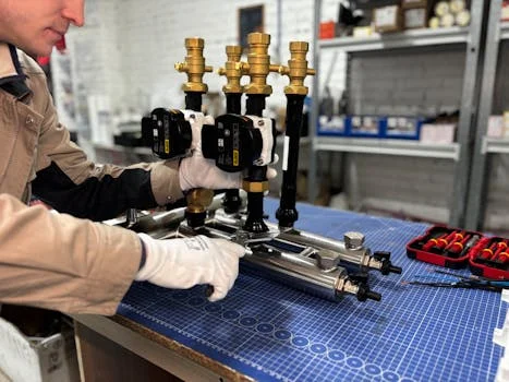
To achieve near-total water recovery and meet the most stringent discharge limits, a hybrid ZLD system integrates physical, chemical, and thermal separation technologies. This design ensures that each stage operates within its optimal parameter range, protecting downstream components and maximizing efficiency.
Stage 1: Dissolved Air Flotation (DAF) for TSS and FOG Removal
The primary treatment stage utilizes a high-efficiency DAF system for silicon particle removal. By introducing microbubbles (30-50 μm) into the wastewater, suspended silicon particles and residual oils from the sawing process are floated to the surface for mechanical skimming. This stage is critical for removing 95-98% of TSS, which would otherwise cause rapid fouling of RO membranes. (HydropureWater field data, 2025). The addition of specific coagulants and flocculants during this stage helps bridge smaller silicon particles into larger flocs, significantly increasing the buoyancy and removal rate of the solids.
Stage 2: Reverse Osmosis (RO) for Desalination and Fluoride Removal
Following clarification, the effluent enters a multi-stage RO system for desalination and fluoride removal. Using low-fouling polyamide thin-film composite (TFC) membranes specifically selected for HF resistance, this stage recovers 90-95% of the water as high-quality permeate suitable for reuse in non-critical fab processes. The system reduces Total Dissolved Solids (TDS) from 5,000 mg/L to less than 50 mg/L. In the RO stage, secondary concentration cycles are often employed to push the recovery limits toward the 95% threshold. This involves high-pressure pumps capable of overcoming the osmotic pressure of the brine, ensuring that the volume of waste sent to the MVR is minimized, thereby significantly reducing the overall energy footprint of the thermal evaporation process.
Stage 3: Mechanical Vapor Recompression (MVR) for Brine Concentration
The RO concentrate (brine) is fed into an MVR evaporator. This thermal process uses mechanical energy to compress vapor, increasing its temperature and allowing it to be reused as a heating medium. This reduces the brine volume by another 90-95%, leaving only a small amount of concentrated slurry or solid salt for disposal. Energy consumption is maintained at a highly efficient 20-30 kWh/m³ of distillate. By integrating a final crystallizer or a high-efficiency spray dryer, the remaining liquid is eliminated entirely, achieving the true zero liquid discharge status required for modern environmental certifications.
| Parameter | Raw Influent | Post-DAF Effluent | Post-RO Permeate | ZLD System Final |
|---|---|---|---|---|
| TSS (mg/L) | 500 - 2,000 | 10 - 50 | < 1 | 0 (Solid Recovery) |
| Fluoride (mg/L) | 50 - 200 | 10 - 15 | < 5 | < 1 |
| TDS (mg/L) | 1,000 - 5,000 | 900 - 4,500 | < 50 | N/A (Distillate) |
| Recovery Rate | - | N/A | 90 - 95% | 99.8% |
This process flow ensures that the real-world silicon wafer wastewater treatment project with 99.8% recovery remains stable despite fluctuations in influent chemistry.
Cost Breakdown: CAPEX, OPEX, and ROI for a 100 m³/day Hybrid ZLD System
For procurement teams, the transition to a ZLD model is justified through a combination of avoided regulatory penalties and significant water reuse savings. Based on 2025 benchmarks for a 100 m³/day facility, the total investment reflects the high-specification materials required for acid resistance and automation.
CAPEX Breakdown ($1.2M – $1.8M Total):
- DAF System: $200,000 – $350,000. Includes stainless steel tankage and microbubble generators.
- RO System (JY Series): $400,000 – $600,000. Includes high-pressure pumps and HF-resistant membranes.
- MVR System: $300,000 – $500,000. Custom-engineered titanium heat exchangers for corrosion resistance.
- Automation/PLC: $100,000 – $150,000. Centralized control for real-time monitoring of fluoride and pH levels.
OPEX Analysis ($0.80 – $1.20/m³ Treated):
Operational costs are dominated by energy (60%), primarily driven by the MVR stage. However, the use of PLC-controlled chemical dosing for pH adjustment and coagulation optimizes chemical consumption, reducing costs by 15% compared to manual dosing. Chemicals (coagulants, antiscalants) account for $0.20–$0.30/m³, while labor for one full-time equivalent (FTE) adds approximately $0.15–$0.25/m³. A critical factor in the ROI calculation is the reduction in hazardous waste disposal fees. By concentrating silicon sludge into a dry cake using advanced mechanical dewatering, facilities can reduce their waste volume by up to 80%, leading to annual savings that often exceed $30,000 in logistics and landfill surcharges alone.
| Cost Category | Conventional Treatment | Hybrid ZLD System | Net Impact |
|---|---|---|---|
| CAPEX | $400,000 | $1,500,000 | +$1.1M Investment |
| Annual OPEX | $180,000 (Incl. Discharge Fees) | $40,000 (Low discharge) | $140,000 Savings/yr |
| Water Savings | $0 | $50,000/yr | $50,000 Savings/yr |
| Avoided Fines | $50,000 (Avg. risk/yr) | $0 | $50,000 Savings/yr |
| Payback Period | N/A | 2.5 - 3.5 Years | High ROI |
This financial model demonstrates that while the initial investment is higher, the solar cell wastewater engineering solutions with hybrid ZLD design provide long-term fiscal stability against rising water prices and environmental taxes.
Compliance Checklist: Meeting China GB and EPA Standards for Silicon Wastewater
EHS compliance officers must adhere to a rigorous monitoring schedule to ensure the facility remains within legal thresholds. The hybrid ZLD system is designed to meet both China GB 8978-1996 and EPA 40 CFR Part 469 (Semiconductor Category) standards, which differ slightly in their stringency and reporting requirements.
- Fluoride Compliance: China GB requires <10 mg/L daily average. EPA Part 469 is stricter, requiring <3.0 mg/L monthly average. The hybrid system targets <1 mg/L to provide a safety buffer.
- Total Suspended Solids (TSS): GB limits are 70 mg/L, while EPA requires <20 mg/L. The DAF+RO combination typically achieves <1 mg/L, exceeding both standards.
- pH Balance: Both standards require a range of 6.0 to 9.0. This is managed via an automatic chemical dosing system that adjusts based on influent acidity.
- Phosphorus: GB Class I limits total phosphorus (P) to 0.5 mg/L. Phosphorus removal is integrated into the coagulation/flocculation step of the DAF process.
3-Step Compliance Audit Process:
- Influent Characterization: Weekly 24-hour composite sampling to track fluctuations in HF and silicon loading.
- Performance Validation: Real-time monitoring of RO permeate conductivity and MVR distillate purity.
- Continuous Monitoring Setup: Installation of online Ion-Selective Electrode (ISE) sensors for fluoride and gravimetric analysis protocols for TSS as per EPA 160.2.
Modern compliance also demands rigorous data logging. Systems must now include digital twin interfaces that record every pH fluctuation and fluoride spike, providing a transparent audit trail for environmental inspectors. This automation reduces the margin for human error during the high-pressure reporting cycles required by the EPA and local environmental bureaus. For facilities handling high-concentration streams, specialized HF wastewater treatment solutions for fluoride recovery may be integrated to further reduce the chemical load on the ZLD system.
Implementation Roadmap: 6 Steps to Deploy a Hybrid ZLD System in 12 Weeks
Deploying a technical ZLD system requires precise coordination between engineering, civil works, and regulatory bodies. A 12-week schedule is achievable with a modular equipment approach.
- Step 1: Characterization (Weeks 1-2): Conduct 24-hour composite sampling. Identify peak flow rates (e.g., 150 m³/day) to size equalization tanks.
- Step 2: Sizing & Selection (Weeks 3-4): Select high-specification components, including the high-efficiency DAF system and RO units. Verify vendor compliance with local environmental codes.
- Step 3: Site Preparation (Weeks 5-6): Design foundations for skids (500 kg/m² load capacity). Establish utility headers for power (400V), compressed air, and CIP water.
- Step 4: Installation (Weeks 7-9): Position skids. Conduct 48-hour jar testing for DAF to optimize coagulant dosage (typically 50-100 mg/L PAC). Soak RO membranes in 1% citric acid to remove shipping preservatives.
- Step 5: Validation & Training (Weeks 10-11): Execute a 7-day continuous run. Train operators on RO system maintenance and cleaning protocols, focusing on alarm response and chemical safety.
- Step 6: Handover (Week 12): Submit final compliance reports to the local EPA or DEQ. Establish a 1-year spare parts inventory.
During the validation phase, it is essential to conduct stress tests on the MVR's heat exchangers to ensure they can handle the specific scaling tendencies of the concentrated silicon brine. This proactive testing prevents heat transfer efficiency losses that typically plague systems in their first six months of operation. Furthermore, establishing a remote monitoring link during Week 12 allows for real-time troubleshooting by specialists, ensuring the 99.8% recovery target is maintained consistently.
Related Equipment
The following HydropureWater products are engineered for the wastewater challenges discussed above:
- filter press for silicon sludge dewatering and recovery — view specifications, capacity range, and technical data. The selection of a high-pressure filter press is particularly vital for monocrystalline lines, as the resulting silicon-rich sludge can sometimes be reclaimed for secondary industrial applications, turning a waste stream into a potential minor revenue source for the facility.
Need a customized solution? Request a free quote with your specific flow rate and pollutant parameters to receive a detailed engineering proposal and recovery projection.