Integrated Circuit HF Wastewater Treatment: 2025 Engineering Specs, Hybrid System Design & 99.8% Fluoride Recovery Blueprint
IC fabs generate HF wastewater with fluoride concentrations up to 5,000 mg/L, requiring treatment systems that achieve <10 mg/L discharge limits (China GB 31573-2015) or <4 mg/L (US EPA). Hybrid systems combining double-membrane filtration, CaF2 crystallization, and sludge recycling recover up to 99.8% of fluoride while reducing waste disposal costs by 40–60%. This blueprint details 2025 engineering specs, system design parameters, and a cost breakdown for a 200 m³/h ZLD installation, including CAPEX ($1.2M–$1.8M) and OPEX ($0.80–$1.20/m³).
Why IC Fabs Need Specialized HF Wastewater Treatment Systems
HF wastewater from integrated circuit manufacturing presents significant environmental and economic challenges, necessitating advanced treatment solutions. IC manufacturing processes, particularly wet etching and chemical vapor deposition (CVD) chamber cleaning, are primary sources of hydrofluoric acid (HF) wastewater. These streams typically contain fluoride concentrations ranging from 1,000 to 5,000 mg/L, with individual fab lines generating flow rates between 50 and 500 m³/h. Untreated discharge of this wastewater poses severe risks to ecosystems and human health.
Regulatory pressure on semiconductor wastewater treatment is intensifying globally. China's GB 31573-2015 standard mandates fluoride discharge limits of ≤10 mg/L, while the US EPA sets a secondary maximum contaminant level (MCL) of ≤4 mg/L, with some states like California enforcing even stricter limits (e.g., ≤2 mg/L). The EU Industrial Emissions Directive also specifies fluoride limits of ≤15 mg/L, pushing for Best Available Techniques (BAT) that often imply zero liquid discharge (ZLD) for new facilities. Non-compliance can lead to severe penalties, including production halts and fines up to $500,000 per year, according to 2024 China MEE data.
Beyond regulatory compliance, the cost drivers for managing HF wastewater are substantial. Disposal costs for untreated HF wastewater can range from $3 to $8 per cubic meter, compounded by rising landfill fees and increasingly stringent hazardous waste classifications. the carbon footprint associated with fluorinated chemicals, which contribute over 30% of fab greenhouse gas emissions (Top 5 research), introduces carbon tax implications. Addressing these costs is crucial for operational sustainability.
Sustainability goals further underscore the need for efficient fluoride recovery IC manufacturing. China’s 2060 carbon neutrality pledge and the global IC industry's commitments, such as the SEMI EHS Roadmap 2023, target a 30% reduction in fluorine footprints by 2030. Implementing advanced hydrofluoric acid neutralization and recovery systems is essential for fabs to meet these ambitious environmental targets and enhance their corporate social responsibility profile.
Hybrid System Design: Combining Membrane Filtration, Crystallization, and Sludge Recycling

Hybrid systems offer a robust and highly efficient approach to integrated circuit HF wastewater treatment, achieving superior fluoride removal and recovery compared to conventional methods. A typical hybrid system integrates double-membrane filtration, CaF2 crystallization, and sludge recycling to maximize efficiency and minimize waste. This multi-stage approach ensures acid-alkaline wastewater treatment for IC fabs is comprehensive.
Double-membrane filtration, typically combining ultrafiltration (UF) and reverse osmosis (RO), is critical for initial fluoride reduction and water reuse. UF acts as a pretreatment, removing suspended solids and colloids, using PVDF or PES membranes with pore sizes ranging from 0.01 to 0.1 μm. The UF permeate then feeds into RO systems for fluoride removal in IC wastewater. RO, utilizing polyamide membranes with pore sizes of 0.001–0.01 μm and operating pressures between 10–60 bar, achieves 95–98% fluoride removal. The RO permeate can meet <1 mg/L fluoride, making it suitable for reuse in IC manufacturing processes (per 2024 WEFTEC benchmarks).
Following membrane treatment, CaF2 crystallization, often implemented using a Crystalactor or similar fluidized bed reactor, precipitates fluoride as dense calcium fluoride pellets. This method significantly reduces sludge volume by 80% compared to traditional lime treatment (Top 1 data), transforming a hazardous waste into a potentially recoverable resource. Optimal crystallization reactor specs include maintaining a pH of 8–10, a Ca²⁺/F⁻ molar ratio of 1.2:1, and a retention time of 30–60 minutes. Precise chemical dosing for CaF2 crystallization reactors is crucial for efficient precipitation and crystal growth.
Sludge recycling closes the loop on fluoride recovery. Research indicates that sludge recycling can recover approximately 32% of total fluorine from the wastewater stream (Top 5 research). This involves thermal or chemical extraction methods, such as acid leaching or pyrolysis, to separate high-purity CaF2 from the sludge. The recovered CaF2 can then be reused in various industries, including potentially back into certain IC manufacturing processes if purity requirements of >99.5% CaF2 are met, contributing to a circular economy for fluoride.
A typical 3-stage process flow for IC fab ZLD systems involves: Stage 1: Pretreatment & Initial Fluoride Removal, where raw HF wastewater (e.g., 5,000 mg/L fluoride) is neutralized and partially precipitated to approximately 500 mg/L. Stage 2: Membrane Filtration, where the pretreated water undergoes UF and RO, reducing fluoride concentrations further to around 50 mg/L. Stage 3: CaF2 Crystallization & Sludge Recycling, where the remaining fluoride is crystallized to achieve final effluent quality of <10 mg/L, with sludge processed for fluoride recovery. This comprehensive approach ensures maximum removal efficiency and resource recovery.
| Process Stage | Key Technology | Influent Fluoride (mg/L) | Effluent Fluoride (mg/L) | Fluoride Removal Efficiency |
|---|---|---|---|---|
| Pretreatment | Coagulation/Flocculation, pH Adjustment | 1,000 – 5,000 | 200 – 500 | 80 – 90% |
| Membrane Filtration | UF + RO | 200 – 500 | 1 – 50 | 95 – 98% |
| CaF2 Crystallization | Fluidized Bed Reactor | 1 – 50 | <10 (GB), <4 (US EPA) | 90 – 99% |
| Overall Hybrid System | Integrated Process | 1,000 – 5,000 | <10 (GB), <4 (US EPA) | Up to 99.8% |
Hybrid System Specifications for IC Fabs: Engineering Parameters and Footprint
Detailed engineering specifications are crucial for IC fab environmental engineers and procurement leads to accurately size systems, compare vendor offerings, and estimate installation requirements. HydropureWater offers standard hybrid system models designed for various flow rates, ensuring scalability and efficiency for diverse fab operations.
System capacity options typically range from 50 m³/h to 500 m³/h. A standard 200 m³/h hybrid system for integrated circuit HF wastewater treatment requires an approximate footprint of 12m × 8m × 4m (L×W×H), including all primary treatment units, chemical storage, and control systems. Modular expansion options are available, allowing fabs to scale treatment capacity as production demands increase without extensive re-engineering.
Energy consumption for these advanced systems is optimized. The membrane stage (UF+RO) typically consumes 0.5–1.0 kWh/m³, while the CaF2 crystallization process adds 0.3–0.5 kWh/m³. The overall energy consumption for a hybrid system ranges from 0.8–1.5 kWh/m³, which is a significant improvement over conventional lime treatment (1.2–2.0 kWh/m³) and drastically lower than evaporation-based ZLD systems (5–10 kWh/m³).
Chemical consumption is precisely controlled for optimal performance. Lime (Ca(OH)₂) dosing is typically required at 1.2–1.5 kg/m³ to facilitate fluoride precipitation, while sulfuric acid (H₂SO₄) for pH adjustment consumes 0.1–0.3 kg/m³. Automatic chemical dosing systems are equipped with ±2% accuracy and often include redundancy to ensure continuous and stable operation, critical for maintaining consistent effluent quality and preventing upsets in the CaF2 crystallization process.
Effluent quality from HydropureWater's hybrid systems consistently meets or exceeds stringent regulatory standards. Fluoride concentrations are reliably reduced to <10 mg/L for China GB 31573-2015 compliance and <4 mg/L for US EPA limits. Total Suspended Solids (TSS) are typically <30 mg/L, and pH is maintained within the 6–9 range. A 2024 case study from a Shanghai fab demonstrated 99.8% fluoride removal efficiency, underscoring the system's robust performance in real-world IC fab ZLD systems.
Sludge production from hybrid systems is significantly reduced. Dry basis sludge production ranges from 0.5–1.0 kg/m³, representing an 80% volume reduction compared to conventional lime treatment. Sludge dewatering is efficiently handled by filter presses for CaF2 sludge dewatering, producing a filter cake with 20–30% solids content, suitable for further fluoride recovery or minimized disposal.
| Parameter | Specification (200 m³/h System) | Notes |
|---|---|---|
| Capacity Range | 50, 100, 200, 500 m³/h (modular) | Scalable design for IC fab operations |
| Footprint (200 m³/h) | 12m × 8m × 4m (L×W×H) | Includes main treatment units, chemical storage |
| Energy Consumption | 0.8 – 1.5 kWh/m³ (overall) | Membrane: 0.5-1.0 kWh/m³; Crystallization: 0.3-0.5 kWh/m³ |
| Lime (Ca(OH)₂) Dosing | 1.2 – 1.5 kg/m³ | For CaF2 precipitation |
| Sulfuric Acid (H₂SO₄) Dosing | 0.1 – 0.3 kg/m³ | For pH adjustment |
| Effluent Fluoride (China GB) | <10 mg/L | Meets GB 31573-2015 |
| Effluent Fluoride (US EPA) | <4 mg/L | Meets secondary MCL |
| Sludge Production (dry basis) | 0.5 – 1.0 kg/m³ | 80% volume reduction vs. lime treatment |
| Sludge Solids Content | 20 – 30% | Achieved by plate-frame filter press |
Treatment Method Comparison: Hybrid vs. Conventional Systems
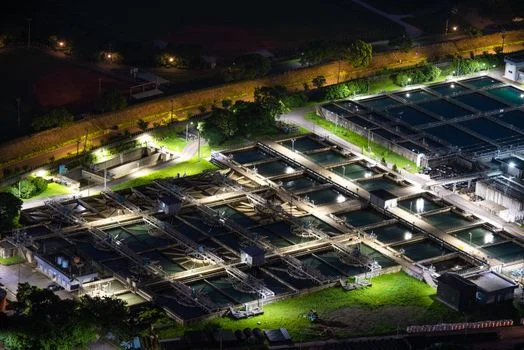
Selecting the optimal integrated circuit HF wastewater treatment method requires a thorough evaluation of efficiency, cost, and compliance. Hybrid systems, conventional lime treatment, and evaporation-based Zero Liquid Discharge (ZLD) each offer distinct advantages and disadvantages, making them suitable for different fab operational contexts and regulatory environments.
| Feature | Hybrid System (Membrane+Crystallization+Sludge Recycling) | Conventional Lime Treatment | Evaporation (ZLD) |
|---|---|---|---|
| Fluoride Removal Efficiency | 99.8% | 90% | 99.9% (near-total) |
| Sludge Production (dry basis) | 0.5 – 1.0 kg/m³ | 2 – 3 kg/m³ | 0.1 kg/m³ (solid waste) |
| Energy Consumption | 0.8 – 1.5 kWh/m³ | 1.2 – 2.0 kWh/m³ | 5 – 10 kWh/m³ |
| CAPEX (for 200 m³/h) | $1.2M – $1.8M | $500K – $800K | $2M – $3M |
| OPEX | $0.80 – $1.20/m³ | $1.00 – $1.50/m³ | $2.00 – $3.00/m³ |
| Fluoride Recovery Potential | High (up to 32% from sludge) | Low (sludge disposal) | Low (concentrated brine/solid waste) |
| Water Reuse Potential | High (RO permeate for fab reuse) | Limited (requires polishing) | Very High (distillate for fab reuse) |
| Footprint | Medium | Small | Large |
Use-Case Matching: Hybrid systems are ideal for IC fabs with flow rates ranging from 50–500 m³/h that prioritize both stringent compliance and sustainability goals, including fluoride recovery IC manufacturing. Their balance of high efficiency, moderate operating costs, and resource recovery makes them a strategic investment. Conventional lime treatment is typically considered for low-budget retrofits or smaller fabs where discharge limits are less stringent, though it often requires additional polishing steps to meet modern standards. Evaporation-based ZLD systems are best suited for fabs in water-scarce regions or those facing extremely strict discharge regulations that demand zero liquid discharge, despite their significantly higher energy consumption and capital costs.
Compliance Alignment: Hybrid systems are designed to meet both China GB 31573-2015 (≤10 mg/L) and US EPA (≤4 mg/L) fluoride limits, often achieving even lower concentrations. Lime treatment alone may struggle to consistently meet these tighter limits without further advanced polishing steps, potentially leading to non-compliance risks. Evaporation, by its nature, achieves ZLD, eliminating discharge entirely and thus ensuring compliance with the most stringent regulations, though at a premium cost for energy.
ZLD Cost Breakdown: CAPEX, OPEX, and ROI for a 200 m³/h IC Wastewater System
Investing in a hybrid ZLD system for integrated circuit HF wastewater treatment yields substantial financial benefits through reduced disposal costs and potential revenue from fluoride recovery. A detailed cost analysis is essential for budgeting and justifying the capital expenditure for such an upgrade or new installation. For a more detailed cost analysis for HF wastewater treatment, refer to our dedicated article.
| Cost Category | Component | Estimated Cost (200 m³/h System) | Notes |
|---|---|---|---|
| CAPEX (Capital Expenditure) | Equipment (Membrane, Crystallizer, Sludge Dewatering, Tanks, Pumps) | $800,000 – $1,200,000 | Core treatment units |
| Installation & Civil Works | $200,000 – $300,000 | Site preparation, piping, electrical, structural | |
| Engineering & Project Management | $100,000 – $200,000 | Design, permits, commissioning | |
| Permitting & Contingency | $50,000 – $100,000 | Regulatory approvals, unforeseen costs | |
| Total Estimated CAPEX | $1,200,000 – $1,800,000 | Excludes land cost; membrane replacement every 3-5 years ($50K-$100K) | |
| OPEX (Operating Expenditure) per m³ | Energy Consumption | $0.30 – $0.50/m³ | Based on 0.8-1.5 kWh/m³ at $0.30/kWh (regional variation) |
| Chemicals (Lime, Acid, Antiscalant) | $0.20 – $0.40/m³ | Varies with influent concentration and chemical prices | |
| Labor & Maintenance | $0.10 – $0.20/m³ | Includes routine checks, membrane cleaning, minor repairs | |
| Sludge Disposal (post-dewatering) | $0.20 – $0.30/m³ | Significantly reduced compared to untreated sludge | |
| Total Estimated OPEX | $0.80 – $1.20/m³ | Excludes potential fluoride recovery revenue | |
The CAPEX breakdown highlights that equipment costs constitute the largest portion, ranging from $800,000 to $1,200,000 for a 200 m³/h system. Installation, engineering, and permitting add another $350,000–$600,000. It is crucial to account for membrane replacement, which occurs every 3–5 years and costs $50,000–$100,000 per cycle. The total estimated CAPEX for a 200 m³/h IC fab ZLD system typically falls between $1.2M and $1.8M.
OPEX for hybrid systems is highly competitive. Energy costs, ranging from $0.30–$0.50/m³, represent a significant portion, followed by chemical consumption ($0.20–$0.40/m³). Labor and maintenance are estimated at $0.10–$0.20/m³, and significantly reduced sludge disposal costs are $0.20–$0.30/m³. The total OPEX for treating HF wastewater is $0.80–$1.20/m³. This is a substantial reduction compared to the $3–$8/m³ cost of disposing of untreated HF wastewater, which is a major driver for adopting advanced treatment.
The Return on Investment (ROI) for hybrid systems is compelling, with a typical payback period of 3–5 years. This rapid ROI is driven by two main factors: reduced disposal costs and potential revenue from fluoride recovery. For a 200 m³/h system operating 24/7, annual savings from reduced disposal alone can amount to $400,000–$600,000 (assuming an average $2/m³ saving on 1,752,000 m³/year). Additionally, the recovery of high-purity CaF2, which can be sold for $50–$100 per ton, provides an extra revenue stream. If 32% of fluoride (from a 3,000 mg/L influent) is recovered from the sludge, a 200 m³/h system could potentially recover several hundred tons of CaF2 annually, adding further to the financial benefits. These factors make the investment in fluoride recovery IC manufacturing highly attractive.
Financing options are available to support these investments. Government subsidies, such as China’s 2025 Green Manufacturing Fund, offer incentives for adopting sustainable technologies. Leasing programs and performance-based contracts (e.g., pay-per-m³ treated models) can also help fabs manage initial capital outlay and align costs with operational output.
Compliance Roadmap: Meeting China GB and US EPA Fluoride Limits

Navigating the complex landscape of wastewater discharge regulations is paramount for IC fab EHS managers. Implementing a robust integrated circuit HF wastewater treatment system must align with current national and regional standards and be future-proofed for stricter limits. For a broader understanding of global wastewater discharge standards for semiconductor fabs, consult our specialized article.
China GB 31573-2015: This national standard for Discharge Standard of Water Pollutants for Electroplating sets a fluoride discharge limit of ≤10 mg/L for the semiconductor industry. Additionally, pH must be maintained between 6 and 9, and Total Suspended Solids (TSS) ≤30 mg/L. Compliance requires continuous monitoring with fluoride sensors at discharge points, complemented by quarterly laboratory testing to ensure accuracy and consistency. Our hybrid systems are engineered to consistently achieve fluoride levels well below this threshold.
US EPA Standards: The US Environmental Protection Agency sets fluoride limits under the Clean Water Act. While there isn't a direct federal discharge standard specifically for fluoride from IC fabs, the secondary Maximum Contaminant Level (MCL) for drinking water is ≤4 mg/L, often used as a benchmark for industrial discharge. State-specific limits can be even more stringent; for example, California often mandates ≤2 mg/L. For indirect discharge into Publicly Owned Treatment Works (POTWs), facilities must comply with pretreatment standards outlined in 40 CFR Part 469 (Electrical and Electronic Components Point Source Category), which typically require removal of toxic pollutants to prevent interference with POTW operations or pass-through into receiving waters. Our systems are designed to meet these stringent requirements, including those for fluoride recovery IC manufacturing.
EU Industrial Emissions Directive (IED): The IED (Directive 2010/75/EU) requires industrial installations to obtain permits based on Best Available Techniques (BAT). For new fabs, BAT often implies zero liquid discharge (ZLD) for specific waste streams, including those with high fluoride concentrations. For existing facilities, compliance timelines are typically set, with 2027 being a common target for implementing BAT conclusions. The IED generally sets a fluoride limit of ≤15 mg/L, but local permits can be much tighter, often pushing towards ZLD solutions for semiconductor wastewater treatment.
Future-Proofing Compliance: Regulatory trends indicate a global movement towards stricter discharge limits and greater emphasis on resource recovery. Fabs should design their integrated circuit HF wastewater treatment systems for potential future limits, such as China’s projected 2030 target of ≤5 mg/L fluoride. This can be achieved through modular upgrades, such as adding a final polishing RO stage or advanced ion exchange post-crystallization, ensuring long-term compliance without needing entirely new infrastructure.
Frequently Asked Questions
What is the typical fluoride concentration in IC fab HF wastewater?
IC fab HF wastewater typically contains fluoride concentrations ranging from 1,000–5,000 mg/L. This concentration varies depending on specific etching processes, with higher concentrations like 3,000 mg/L often seen in advanced 300mm wafer manufacturing.
How does CaF2 crystallization compare to lime treatment for fluoride removal?
CaF2 crystallization is significantly more efficient than traditional lime treatment for fluoride removal. Crystallization produces 80% less sludge and achieves up to 99.8% fluoride removal, while lime treatment typically achieves around 90%. Crystallization requires precise pH control (8–10) and specific Ca²⁺/F⁻ molar ratios for optimal performance.
What is the payback period for a hybrid HF wastewater treatment system?
The typical payback period for a hybrid HF wastewater treatment system is 3–5 years. This rapid return on investment is primarily driven by substantial reductions in disposal costs (saving $3–$8/m³ for untreated wastewater versus $0.80–$1.20/m³ for treated) and potential revenue generated from fluoride recovery, which can yield $50–$100 per ton of recovered CaF2.
Can hybrid systems achieve zero liquid discharge (ZLD) for IC wastewater?
Yes, hybrid systems can be designed to achieve zero liquid discharge (ZLD) for IC wastewater, but this often entails higher energy costs (5–10 kWh/m³). ZLD is achieved by integrating additional advanced stages like multi-effect evaporation or brine crystallization, which can increase the overall CAPEX by 30–50%.
What are the maintenance requirements for a hybrid HF wastewater system?
Maintenance requirements for a hybrid HF wastewater system include routine tasks such as membrane cleaning (typically weekly), chemical dosing calibration (daily), and sludge dewatering operations (continuous). Additionally, membranes require replacement every 3–5 years, incurring a cost of approximately $50,000–$100,000 per replacement cycle.