Cavitation air flotation (CAF) systems remove suspended solids, fats, oils, and grease (FOG) from industrial wastewater by generating microbubbles (30–100 μm) via hydrodynamic cavitation, without external compressors or pressure tanks. A high-speed impeller (900–1,500 RPM) creates a vacuum that draws in air and shears it into bubbles that attach to contaminants and float them for skimming. Reported operating ranges include 92–97% TSS removal and 85–95% FOG reduction at influent concentrations of 50–500 mg/L, with energy use often 30–50% lower than dissolved air flotation (DAF).
How cavitation air flotation (CAF) systems work
Cavitation air flotation (CAF) systems spin an impeller at 900–1,500 RPM, forming a −0.5 to −0.8 bar vacuum that shears air into 30–100 μm microbubbles. Bubbles attach to FOG and solids, rise in 10–20 minutes, and are skimmed. Pretreatment effluent typically exits below 50 mg/L TSS and 30 mg/L FOG.CAF process reports commonly state suspended solids removal over 90%. Over 95% is common when coagulant and flocculant dosing is optimized.
Why Factories Are Switching from DAF to CAF for Wastewater Pretreatment
Food processing plants with high FOG loads often see dissolved air flotation (DAF) units clog when saturation trains scale or nozzles foul. Facilities that switch to CAF commonly report up to 30% less downtime because there is no pressure vessel or compressor train. CAF also uses 30–50% less energy than DAF per cubic meter under comparable FOG pretreatment duty.
CAF tolerates variable influent better than many pressurized trains. That suits batch food lines and mills with swing loads. Food plants use it for FOG, and pulp mills use it for fibers and ink. Textile plants report up to 90% dye and surfactant separation. Metalworking shops float free oils and fines. Municipal plants apply CAF as pretreatment to cut BOD before sewer discharge.
The Science of Cavitation: How Microbubbles Form Without Pressure Tanks
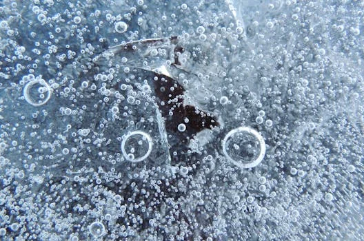
Hydrodynamic cavitation drives microbubble generation in CAF units through localized pressure drops that form and collapse vapor cavities in the liquid. The mechanism differs from acoustic cavitation, which relies on sound waves. Bernoulli’s principle governs the impeller zone: as tip speed rises, pressure falls and ambient air is drawn through a central shaft into the high-shear region.
Centrifugal force and turbulence shear that air into a dense cloud of 30–100 μm bubbles. That size band offers 10–15 times more attachment area than coarser induced-air bubbles. Some CAF aerators run near 1,700 RPM. Manufacturer documentation reports roughly four times the air mass a comparable DAF dissolves. The CAF impeller whips air into wastewater much like a blender aerates a liquid.
Step-by-Step: How a CAF System Removes Contaminants from Wastewater
A CAF train removes contaminants through a multi-stage physical-chemical sequence sized for suspended solids and FOG separation. Each stage has measurable setpoints that control removal efficiency.
- Step 1: Influent Equalization and pH Adjustment. Raw industrial wastewater first enters an equalization tank to buffer flow and concentration fluctuations, ensuring a consistent feed to the CAF unit. Optimal bubble attachment and coagulant performance typically occur within a pH range of 6.5–8.5. Automated chemical dosing systems are often integrated to adjust pH using sulfuric acid or sodium hydroxide as needed, and to introduce coagulants like polyaluminum chloride (PAC) or ferric chloride.
- Step 2: Aerator Operation. The heart of the CAF system is the aerator, featuring a high-speed impeller rotating between 900–1,500 RPM. This rotation creates a powerful vacuum, typically ranging from -0.5 to -0.8 bar, which pulls atmospheric air into the wastewater stream. The impeller shears this air into a dense microbubble cloud of 30–100 μm. About 70% of bubbles fall in the 50–80 μm range that favors contaminant adhesion.
- Step 3: Bubble-Particle Attachment. Within the flotation tank, the generated microbubbles intimately mix with the pre-conditioned wastewater. Fats, oils, grease (FOG), and many suspended solids are naturally hydrophobic, meaning they repel water and readily adhere to the air-water interface of the microbubbles via surface tension and electrostatic forces. For hydrophilic particles or finely dispersed colloids, the addition of coagulants (e.g., PAC or ferric chloride) and flocculants (e.g., anionic polymers) is essential to destabilize charges and promote agglomeration, enhancing bubble attachment.
- Step 4: Flotation and Skimming. Once attached, the buoyant bubble-contaminant aggregates rapidly rise to the surface of the flotation tank, forming a concentrated sludge blanket. The typical hydraulic retention time (HRT) in the flotation tank ranges from 10–20 minutes, with a surface loading rate of 5–10 m³/m²·h. A mechanical skimmer then continuously removes this floated sludge from the surface, which typically has a solids content of 2–5%, minimizing carryover into the clarified effluent.
- Step 5: Effluent Discharge. The clarified water, now significantly free of suspended solids and FOG, exits the CAF system for further treatment or discharge. For pre-treatment applications, typical effluent quality benchmarks include TSS concentrations of less than 50 mg/L, FOG levels below 30 mg/L, and a chemical oxygen demand (COD) reduction of 50–70%.
The process flow can be visualized as: Influent → equalization/pH adjustment → automated coagulant dosing for CAF pretreatment → aerator → flotation tank → skimmer → clarified effluent → sludge handling. For precise chemical management, an automatic chemical dosing system is often integrated. Manufacturer design notes also cite flotation-chamber retention near 17 minutes as a practical clarification target for many CAF layouts.
| CAF System Parameter | Typical Operating Range | Impact on Performance |
|---|---|---|
| Impeller RPM | 900–1,500 RPM | Controls vacuum, air intake, and bubble shear intensity. |
| Vacuum Pressure | -0.5 to -0.8 bar | Directly influences air induction rate and bubble formation. |
| Bubble Size Distribution | 30–100 μm (70% in 50–80 μm) | Smaller, uniform bubbles enhance attachment surface area. |
| Optimal pH Range | 6.5–8.5 | Maximizes coagulant efficiency and bubble adhesion. |
| Retention Time | 10–20 minutes | Ensures sufficient contact for bubble-particle attachment. |
| Surface Loading Rate | 5–10 m³/m²·h | Influences solids separation efficiency and tank sizing. |
| Skimmed Sludge Solids | 2–5% | Indicates effective solids concentration and dewatering potential. |
CAF vs DAF: Engineering Specs, Efficiency Data, and Cost Comparison
CAF and DAF both clarify wastewater by flotation, yet they generate bubbles by different physics. That difference drives energy use, maintenance load, footprint, and the particle sizes each train handles best.
| Feature | Cavitation Air Flotation (CAF) | Dissolved Air Flotation (DAF) |
|---|---|---|
| Bubble Generation | Hydrodynamic cavitation (high-speed impeller) | Pressure saturation (dissolved air released under atmospheric pressure) |
| Bubble Size | 30–100 μm (mechanically sheared) | 10–50 μm (pressure-released) |
| Energy Consumption | 0.10–0.25 kWh/m³ (30–50% lower than DAF) | 0.15–0.40 kWh/m³ (requires air compressor for pressure vessel) |
| CAPEX (10–100 m³/h) | $50,000–$200,000 (no pressure tanks) | $80,000–$300,000 (includes pressure vessels, compressors) |
| OPEX (per m³) | $0.10–$0.25 (lower energy, less maintenance) | $0.15–$0.40 (higher energy, more maintenance) |
| Maintenance Requirements | Lower (impeller wear, aerator cleaning) | Higher (pressure vessel scaling, compressor maintenance, nozzle clogging) |
| Footprint | Compact (no separate saturation tank) | Larger (requires saturation tank, compressor skid) |
| Influent Variability Tolerance | High tolerance for FOG and TSS fluctuations | Less tolerant, prone to clogging with high FOG/solids |
| FOG Removal Efficiency | 90–95% (superior for high FOG loads) | 85–90% (can struggle with very high FOG) |
| Fine Particle Removal | Good (with proper chemical conditioning) | Excellent (smaller bubbles better for <30 μm particles) |
CAF gains most of its advantage from mechanical bubble generation. Without pressure tanks, CAPEX falls. Vessel scaling and nozzle clogging also drop out of the failure list. That shift yields 30–50% lower energy use and up to 90% less maintenance downtime in high-FOG service, according to 2024 industry surveys. Manufacturer data for one CAF aerator family lists about 2.5 hp at 20 m³/h and about 3.5 hp up to 150 m³/h because compressors and recycle pumps are omitted.
A Dissolved Air Flotation (DAF) System still wins when the duty needs a dense cloud of <30 μm bubbles for fine particles or low-turbidity water (<50 NTU). Choose CAF when FOG regularly exceeds 200 mg/L, floor space is tight, or energy cost is the main OPEX driver. Choose DAF when fine-particle capture dominates the specification.
When CAF Fails: Troubleshooting Common Operational Issues
CAF uptime depends on impeller condition, chemistry, skimming rate, and motor alignment. The checklist below maps symptoms to causes and fixes for plant engineers.
- Issue 1: Impeller Wear.
- Symptoms: Reduced bubble density, larger bubble size, increased energy draw by the motor, and decreased TSS/FOG removal efficiency.
- Causes: Abrasive suspended solids in the wastewater stream, operating the impeller at excessively high RPMs, or prolonged use beyond its service life.
- Fixes: Implement a routine maintenance schedule to inspect and replace the impeller every 12–18 months, depending on influent abrasiveness. For highly abrasive influent, consider upgrading to ceramic-coated or hardened alloy impellers. Ensure proper screening of influent using devices like a rotary mechanical bar screen to minimize abrasive solids.
- Issue 2: Poor Bubble Attachment.
- Symptoms: Low TSS and FOG removal rates, visible solids in the clarified effluent, and a thin or unstable sludge blanket.
- Causes: Incorrect pH of the wastewater (outside 6.5–8.5 range), insufficient or incorrect type of coagulant/flocculant dosing, or the presence of highly emulsified oils that resist hydrophobic attachment.
- Fixes: Regularly monitor and adjust the pH of the influent to the optimal range of 6.5–8.5 using automated pH control. Conduct jar tests to optimize coagulant and flocculant dosages and select the most effective chemical agents. For emulsified oils, consider upstream pre-treatment with de-emulsifiers (e.g., cationic polymers) or a separate oil-water coalescer.
- Issue 3: Sludge Buildup.
- Symptoms: Reduced effective retention time in the flotation tank, overflow of sludge into the effluent channel, and decreased system capacity.
- Causes: Inadequate skimmer speed or frequency, insufficient sludge pump capacity, or an unexpectedly high solids load exceeding the system's design capacity.
- Fixes: Adjust skimmer speed and frequency to match the sludge generation rate. Verify sludge pump operation and capacity. If consistent high solids loads are the issue, consider increasing the system's design capacity, implementing primary screening, or adding a sludge recirculation loop to enhance solids concentration.
- Issue 4: Energy Spikes.
- Symptoms: Higher than normal kWh/m³ consumption for the aerator motor.
- Causes: Misaligned impeller, fouling of the aerator components (e.g., build-up on the impeller or shaft), or worn motor bearings.
- Fixes: Periodically check and realign the impeller according to manufacturer specifications. Implement a monthly cleaning regimen for the aerator and impeller to prevent fouling. Inspect motor bearings for wear and replace them as part of preventative maintenance.
Which systems improve industrial water treatment efficiency?
Industrial water treatment efficiency rises when the unit matches the pollutant and energy budget. Use CAF for high-FOG TSS flotation at 0.10–0.25 kWh/m³. Use DAF for fine-particle clarification at 0.15–0.40 kWh/m³. Use screens and dosing for load control. Compare specific energy, FOG removal above 200 mg/L, and maintenance hours before buying. Pairing CAF with a Dissolved Air Flotation (DAF) System on the same stream is rarely useful; pick one flotation method for the governing particle size.
Are CAF systems used for high-purity cooling water?
CAF systems are not used for high-purity cooling water or semiconductor UPW loops. They pretreat oily industrial wastewater by floating FOG and solids. Data-centre and fab makeup water needs membranes, ion exchange, or UPW piping instead. Use CAF ahead of biological treatment or sewer discharge when FOG and TSS dominate. Skip CAF when resistivity or silica limits set the water quality target.
Who this is for: plant engineers and EPC teams sizing FOG/TSS pretreatment for food, pulp, textile, or metalworking wastewater. Who should look elsewhere: buyers specifying UPW, closed-loop cooling polish, or sub-30 μm colloidal capture as the primary duty. Next step: send influent TSS, FOG, flow (m³/h), and temperature so a CAF or DAF duty can be checked against the table ranges above.
Frequently Asked Questions
What is the difference between CAF and DAF?
CAF generates 30–100 μm microbubbles with a high-speed impeller and no pressure tank, while DAF releases 10–50 μm bubbles from a pressurized saturator. CAF typically uses 30–50% less energy and handles high FOG loads with fewer nozzle-clogging events. DAF remains stronger for very fine particles below 30 μm because its bubble cloud is finer. Match the technology to particle size and FOG concentration, not to brand preference alone.
What industries use CAF systems?
CAF systems serve food and beverage FOG streams, pulp and paper fiber and ink loads, textile dye and surfactant wastes, metalworking free oils and fines, and municipal pretreatment before sewer discharge. They fit plants that need compact flotation without compressor skids. Removal of free FOG and TSS is the core duty; emulsified oils still need chemical breaking or a coalescer first. Biological polishing follows when dissolved BOD remains above permit limits.
How much does a CAF system cost?
CAF CAPEX typically runs $50,000 at about 10 m³/h to $200,000 at about 100 m³/h, while OPEX is about $0.10–$0.25 per m³ including energy, maintenance, and coagulants. High-FOG sites often recover the CAF-versus-DAF premium in 12–24 months through lower energy and downtime. Final price still depends on metallurgy, sludge handling, and controls scope. Compact plants can also use skid-mounted CAF systems for compact installations.
What is the optimal pH for CAF?
The optimal pH for CAF bubble attachment and coagulant performance is 6.5–8.5 under typical industrial pretreatment conditions. Outside that window, attachment falls and chemical demand rises for the same TSS and FOG targets. Plants usually dose sulfuric acid or sodium hydroxide with automated pH control ahead of the aerator. Confirm the setpoint with jar tests on the actual wastewater matrix before locking PLC limits.
Can CAF remove emulsified oils?
CAF does not reliably remove stable emulsified oils by hydrophobic bubble attachment alone; it targets free FOG and conditioned flocs. Break emulsions first with cationic polymers or a coalescer, then float the released oil. After CAF, residual solids may need secondary clarifiers for downstream CAF effluent polishing. Treat emulsification as a chemistry problem, not an impeller-speed problem.