What Is an Integrated Wastewater Treatment Plant?
An integrated wastewater treatment plant combines screening, biology, clarification, and disinfection in one modular skid or buried tank train. Packaged units commonly treat 1–80 m³/h, deliver 92–97% COD removal and 95%+ TSS reduction under design loading, and need about 0.5 m² per m³/day of capacity at municipal strength and 20–30°C.
Factory-built modules cut civil footprint by up to 60% versus site-built yards and often trim total project CAPEX by 30–40% when concrete and field labor dominate. Units such as the Underground Package Sewage Treatment Plant (WSZ Series) ship ready to connect. Parallel trains can be added later when flow rises. (HydropureWater field data, 2025).
Food processing, textile dyeing, and healthcare sites reuse the same modular shell with different polishing choices. Hospitals and reuse projects often prefer an MBR system for near-reuse-quality effluent when non-potable reuse is required. Designs are checked against US EPA discharge rules, China’s GB 18918-2002 Class A limits, and EU urban wastewater law. Earlier guidance referenced Directive 91/271/EEC; the 2024 revision, Directive (EU) 2024/3019, entered into force on 1 January 2025 and adds stricter nutrient, micropollutant, and energy-neutrality duties (European Commission, 2024).
How Modular Package Plants Work: Step-by-Step Process Flow
The process flow of a modular package plant follows four stages—primary, biological, secondary, and disinfection—and typically reaches 92–97% COD removal when HRT and aeration match influent strength. Each stage targets a defined load with fixed mechanical or biological setpoints. Packing the stages into one footprint shortens pipe runs and reduces wet-weather hydraulic surprises.
Stage 1: Primary Treatment (Solids Removal)
Primary treatment removes settleable solids and coarse debris before biology. Flow usually starts at a rotary mechanical bar screen for coarse solids removal to protect pumps and membranes, then gravity settles in a primary clarifier. Primary sedimentation typically achieves 50–70% TSS removal and 25–40% BOD reduction. For municipal sewage, HRT is held at 1–2 hours at average daily flow.
Stage 2: Biological Treatment (Aerobic Digestion)
Biological treatment uses an Anoxic/Aerobic (A/O) contact-oxidation train. Fixed-film or suspended-growth media, including MBBR carriers at about 500 m²/m³ specific surface area, raise biomass inventory without enlarging the tank. Jet aeration commonly delivers 1.8–2.2 kg O₂/kWh. At 20–30°C, BOD removal reaches 85–95% and NH₃-N removal 70–90%. Municipal HRT is usually 4–8 hours; high-strength industrial streams often need 12–24 hours.
Stage 3: Secondary Clarification (Solids Separation)
After aeration, mixed liquor enters a secondary or lamella clarifier. Inclined plates raise effective settling area while surface loading stays near 20–40 m/h for typical municipal MLSS. Return sludge is set at 50–100% of influent flow to hold MLSS in the bioreactor. Most plants we size for compact sites run near the lower loading end when sludge settleability is average.
Stage 4: Disinfection (Pathogen Removal)
Disinfection finishes the train for discharge or reuse. Options include UV, ozone, or chemical dose from a high-performance chlorine dioxide generator. The target is a 3–4 log (99.9–99.99%) cut in E. coli and fecal coliforms under WHO-style pathogen goals. For ClO₂, 15–30 minutes contact at 1–2 mg/L residual is a common control band.
| Treatment Stage | Key Equipment/Process | Removal Efficiency (Typical) | Engineering Parameter (HRT/Loading) |
|---|---|---|---|
| Primary | Rotary Bar Screen (GX) | 50-70% TSS | 1-2 Hours HRT |
| Biological | A/O Contact Oxidation | 85-95% BOD | 4-8 Hours (Municipal) |
| Secondary | Lamella Clarifier | 95%+ Bio-solids | 20-40 m/h Loading Rate |
| Disinfection | ClO₂ / UV / Ozone | 99.99% Pathogens | 15-30 Mins Contact Time |
What Does an MBBR Process Flow Diagram Show?
An MBBR process flow diagram shows screening, anoxic and aerobic moving-bed reactors with media retention screens, secondary clarification, and disinfection in series. Carrier fill is usually 30–70% of tank volume so media circulate without leaving the reactor. Compared with pure activated sludge, MBBR keeps biomass on the carriers, which stabilizes shock loads when COD swings hour to hour. Return sludge is lower than conventional AS because much of the inventory rides on the media.
What Does an MBR Process Flow Diagram Include?
An MBR process flow diagram includes fine screening, anoxic/aerobic tanks, and immersed or sidestream membranes that replace the secondary clarifier. Membranes hold MLSS near 8,000–12,000 mg/L at 20–30°C, so tank volume shrinks while effluent turbidity stays low enough for many non-potable reuse duties. The trade-off is higher energy for scour air and a need for reliable CIP. When reuse or pathogen barriers matter more than lowest kWh, MBR usually wins the selection meeting.
Integrated vs. Conventional Plants: Key Differences

Modular package systems offer a 30–40% CAPEX cut and a 20–30% OPEX cut versus conventional activated-sludge plants when factory fabrication and automation replace heavy civil work. Spatial efficiency is the clearest split: integrated packages often need about 0.5 m² per m³/day of treated water, while conventional yards commonly occupy 1.5–2.5 m²/m³/day.
Install calendars diverge just as sharply. A site-built plant needs 6–12 months for concrete, piping, and commissioning. A modular integrated train can run within 4–8 weeks after delivery if utilities are ready. PLC automation supports low-staff operation; conventional plants more often keep 24/7 coverage for sludge and blower adjustments.
From a financial view, the 2025 cost breakdown for wastewater treatment plants shows equipment steel may cost more per kilogram, yet total project cost falls when concrete and specialty field labor shrink. Energy use in compact trains often lands at 0.3–0.5 kWh/m³, versus 0.6–1.0 kWh/m³ in many older conventional layouts.
| Parameter | Integrated WWTP | Conventional WWTP |
|---|---|---|
| Footprint | 0.5 m²/m³/day | 1.5–2.5 m²/m³/day |
| CAPEX | $500–$1,200 / m³/day | $800–$2,000 / m³/day |
| OPEX (Energy) | 0.3–0.5 kWh/m³ | 0.6–1.0 kWh/m³ |
| Installation Time | 4–8 Weeks | 6–12 Months |
| Scalability | High (Modular) | Low (Fixed Infrastructure) |
2026 Selection Guide: How to Choose the Right Package Plant
Selecting an integrated wastewater treatment plant for 2026 projects means ranking influent BOD/COD, peak hydraulic factor, and the discharge permit before brand or tank shape. A short framework keeps CAPEX, OPEX, and compliance aligned for the first five years of operation.
Step 1: Define the application. Municipal owners weight low OPEX and simple maintenance. Food and textile plants weight chemical resistance and high COD removal. Remote or buried installs favor portable WSZ-style shells with limited headroom above grade.
Step 2: Calculate required capacity. Use Daily Flow (m³/day) = Peak Hourly Flow (m³/h) × 24 × 1.2 safety factor. A 500-bed hospital at about 300 m³/day still needs roughly 15 m³/h nameplate to cover diurnal peaks.
Step 3: Assess influent characteristics. High FOG can starve biology. Add a high-efficiency DAF system for FOG and TSS removal ahead of the bioreactor when FOG stays elevated. Heavy metals need precipitation before biology, not after.
Step 4: Match technology to compliance. Non-potable reuse for irrigation or cooling favors MBR over A/O because membranes add a physical barrier. Tight sludge yards should add a durable plate and frame filter press to raise cake dryness and cut haulage cost.
| Requirement | Recommended Technology | Typical Application |
|---|---|---|
| High Effluent Quality (Reuse) | MBR (Membrane Bioreactor) | Hotels, Hospitals, Irrigation |
| High FOG/TSS Load | DAF Pretreatment + A/O | Food Processing, Slaughterhouses |
| Space Constraints | Underground Integrated (WSZ) | Residential Areas, Small Factories |
| Variable Flow/Loading | SBR (Sequencing Batch Reactor) | Batch Manufacturing, Rural Towns |
Industrial Wastewater Clarifier Selection Criteria
Industrial wastewater clarifier selection criteria start with design flow, solids loading, overflow rate, and sludge character—not tank brand. Primary units settle raw TSS; secondary units settle biological flocs; DAF replaces gravity when FOG or light solids dominate. Circular scrapers suit steady municipal-like solids; rectangular tanks fit tight plots; lamella packs raise area when footprint is scarce. Keep overflow rate inside the vendor curve for the expected sludge volume index, and size sludge withdrawal for peak solids, not average day.
Case Study: Integrated Treatment for a Food Plant in Kazakhstan
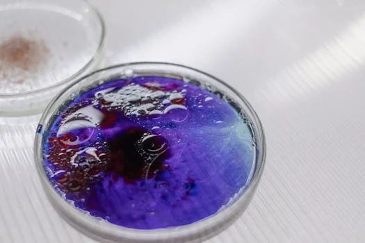
A meat processing facility in Kazakhstan cut FOG by about 99% and met BOD discharge limits below 20 mg/L with a two-stage DAF plus biological integrated train. The plant treated 20 m³/h with BOD at 2,500 mg/L, TSS at 1,800 mg/L, and FOG at 500 mg/L. Those loads would overload a bare A/O package without primary FOG removal.
HydropureWater installed a DAF ahead of an underground WSZ Series integrated plant. The DAF removed over 90% of FOG and suspended solids, protecting the bioreactor from grease blanketing. A/O biology plus ClO₂ disinfection then brought final effluent inside local discharge limits for continuous operation.
Who This Is For / Next Step
This guide is for plant engineers, EPC teams, and procurement managers comparing modular packages against civil WWTPs for 1–80 m³/h duties. Look elsewhere if you need a multi-MLD municipal civil works plant with extensive stormwater tunnels. For a duty-sized proposal, send influent data and permit limits through our request-quote form so the train can be matched to flow, FOG, and reuse goals.
Frequently Asked Questions
What flow range fits an integrated wastewater package?
Most packaged integrated trains are economical from about 1 to 80 m³/h when civil space is limited. Below 1 m³/h, a smaller septic or container unit may cost less. Above 80 m³/h, parallel modules or a hybrid civil layout usually wins on pipe sizing and redundancy. Always size on peak hour with a 1.2 safety factor, not average day alone.
When should I choose MBR over A/O contact oxidation?
Choose MBR when the permit or reuse scheme needs low turbidity and a physical pathogen barrier that clarifiers cannot guarantee. A/O contact oxidation is usually cheaper to run when discharge to sewer or surface water allows higher TSS. MBR MLSS often sits near 8,000–12,000 mg/L at 20–30°C, which shrinks tank volume but raises scour-air power and CIP labor.
Do I need DAF before an integrated biological plant?
Add DAF when FOG or light TSS would coat media, foul membranes, or suppress oxygen transfer. Food, dairy, and slaughterhouse streams with FOG near hundreds of mg/L are the usual triggers. DAF cutting 90%+ FOG ahead of biology is cheaper than recovering a greased reactor. Skip DAF for low-FOG municipal sewage if primary settling already meets the bioreactor’s solids budget.
How long does installation take versus a civil plant?
A modular integrated plant can be online in 4–8 weeks after delivery when power, inlet, and outlet are ready. Conventional civil plants commonly need 6–12 months for concrete and field piping. Factory fabrication shifts risk off the wet site. Weather delays still apply to excavation for buried tanks, so bury and backfill early in the schedule.
Which standards should the effluent design target?
Match the local permit first, then map it to known frameworks such as China’s GB 18918-2002 Class A or US EPA discharge limits for your outfall. For EU projects, keep the older 91/271/EEC baselines in view while planning for Directive (EU) 2024/3019 duties that entered into force on 1 January 2025. Nutrient, micropollutant, and energy-neutrality clauses may change polishing choices even when BOD already passes.