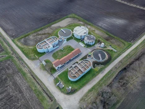
Industrial DAF unit specifications for wastewater typically cover flow from 4 to 300 m³/h, hydraulic loading of 2–10 m/h, recycle of 10–30% of influent, air-to-solids ratios of 0.02–0.06, and bubble sizes of 20–100 μm. At those ranges, TSS, FOG, and colloidal solids removal commonly reaches 90–98% when coagulation and flocculation are controlled. Design drivers include flotation velocity (5–15 m/h) and saturation pressure near 4.0–6.0 bar (58–87 psi). Permit limits follow US EPA 40 CFR Part 403 local programs or EU rules such as Directive 91/271/EEC.
Core DAF Unit Specifications for Process Sizing
A packaged industrial DAF unit for 4–300 m³/h typically delivers 90–98% TSS and 92–99% FOG removal when recycle is 10–30% of flow, hydraulic loading is 2–10 m/h, and the air-to-solids ratio stays at 0.02–0.06 with 20–100 μm bubbles. Saturation pressure is usually 4.0–6.0 bar (58–87 psi), and flotation velocity of 5–15 m/h sets tank area.
Bubble size between 20 and 100 μm controls collision area. Smaller bubbles raise surface area for attachment but need higher saturation pressure, commonly 40–70 psi at the vessel. The dissolved air flotation working principle is physical: microbubbles attach to particles and cut effective density below that of water. The three phases are air dissolution, bubble release on depressurization, and particle–bubble contact in the contact zone.
Recycle rate and saturation pressure govern bubble mass. Diverting 10–30% of clarified effluent through a saturator applies Henry’s Law to dissolve air. When that stream returns to atmospheric pressure in the flotation tank, solubility drops and microbubbles form. Most plants we size for oily food or petrochemical streams run recycle toward the middle of that band unless FOG exceeds about 1,000 mg/L. High-solids or emulsified oil loads often push recycle toward 25–30%. Dissolved Air Flotation (DAF) System packages on the HydropureWater DAF line use that recycle path to keep a uniform bubble blanket across the surface.
Flotation velocity (V_f) sets surface area and typically sits at 5–15 m/h. A common Stokes-form estimate is V_f = (g * (ρ_w - ρ_b) * d_b²) / (18 * μ). Here ρ_w is water density, ρ_b is aggregate density, d_b is bubble diameter, and μ is dynamic viscosity. Sedimentation often settles below 2 m/h; DAF uses upward buoyancy, so hydraulic loading can be higher and footprints run about 60–80% smaller than gravity clarifiers at the same duty.
| Parameter | Standard Range | Impact on Performance |
|---|---|---|
| Bubble Size | 20–100 μm | Smaller bubbles increase surface area for colloidal attachment. |
| Saturation Pressure | 4.0–6.0 bar (58–87 psi) | Higher pressure increases air solubility and bubble density. |
| Recycle Rate | 10–30% of Q | Determines the total mass of air available for flotation. |
| Flotation Velocity | 5–15 m/h | Dictates the required surface area of the flotation tank. |
DAF Performance Benchmarks by Contaminant Type
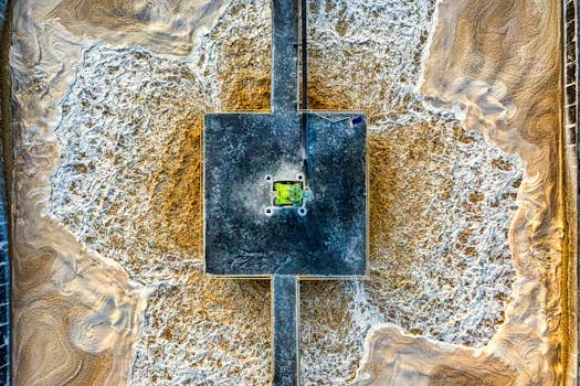
Removal efficiencies for industrial DAF units range from 90% to over 99% for Fats, Oils, and Grease (FOG), depending on influent strength and chemical pretreatment. In the daf water treatment process, clarified quality rises when coagulation and flocculation are tuned first. Using automated polymer dosing systems for DAF pretreatment at 0.5–5 mg/L can enlarge floc and add roughly 10–15% TSS removal versus non-chemically assisted runs.
Industry benchmarks help procurement screen vendors. Poultry plants often see influent FOG of 1,000–2,000 mg/L and need effluent below about 50 mg/L for municipal permits. Petrochemical duties focus on emulsified oil and usually specify 316L stainless steel for chlorides and hydrocarbons. Performance can drop when TDS exceeds 10,000 mg/L because bubble stability and surface tension change.
| Contaminant Type | Influent Range (mg/L) | Removal Efficiency (%) | Typical Industry |
|---|---|---|---|
| Total Suspended Solids (TSS) | 50–500 | 90–98% | Municipal Pre-treatment |
| Fats, Oils, & Grease (FOG) | 100–2,000 | 92–99% | Food & Beverage Processing |
| Chemical Oxygen Demand (COD) | 500–5,000 | 70–90% | Petrochemical / Slaughterhouse |
| Algae / Organics | 10^6–10^8 cells/mL | 85–95% | Aquaculture / Surface Water |
One poultry line using a 50 m³/h DAF unit at 25% recycle with targeted polymer dosing cut FOG from 1,200 mg/L to < 45 mg/L. That change avoided monthly surcharge penalties above $4,000. Aligning equipment to the waste stream matters as much as reading a generic catalog; see also the companion notes on comprehensive 2025 DAF system specifications and standards when you compare skids.
Design Calculations for DAF Units: Formulas and Worked Examples
Hydraulic loading rate (HLR) for modern DAF units is held between 2 and 10 m/h to limit floc shear and keep contact time. Engineers use daf unit design calculations to size tank area and recycle pump duty. Four formulas cover most industrial sizing checks.
- Hydraulic Loading Rate (HLR): HLR = Q / A (m/h), where Q is total flow (m³/h) and A is effective surface area (m²).
- Recycle Rate (R): R = (C_sat - C_in) / (C_in - C_eff) * 100%. This estimates aerated volume needed for a target effluent quality.
- Air-to-Solids Ratio (A/S): A/S = (1.3 * S_a * (f * P - 1) * R) / (Q * X). S_a is air solubility (mg/L), f is saturation efficiency (0.5–0.8), P is pressure in atmospheres, and X is influent solids (mg/L). Target A/S for industrial sludge is 0.02–0.06.
- Bubble Rise Velocity: Estimated via Stokes’ Law so a 100 μm bubble reaches the surface within detention time (typically 20–30 minutes).
Worked Example: An industrial facility has influent TSS (X) of 300 mg/L and flow (Q) of 100 m³/h. Target effluent TSS (C_eff) is 30 mg/L at 5 atm saturation with air solubility (S_a) of 20 mg/L at 20°C.
Using the Recycle Rate formula: R = (20 - 300) / (300 - 30) is not the standard mass-balance path for this duty; instead solve for A/S. With R set at 23%, A/S is:
A/S = (1.3 * 20 * (0.7 * 5 - 1) * 0.23) / (1 * 300) = 0.049.
This 0.049 A/S value sits inside the 0.02–0.06 target band for efficient flotation.
| Symptom | Probable Cause | Engineering Fix |
|---|---|---|
| Poor TSS Removal | Low A/S ratio (< 0.02) | Increase recycle rate or saturation pressure. |
| Turbid Effluent | Inadequate polymer dosing | Optimize automated polymer dosing for larger floc size. |
| Heavy "Float" Sinking | Excessive HLR (> 12 m/h) | Reduce influent flow or increase tank surface area. |
| Large, Bursted Bubbles | Pressure release valve failure | Inspect and clean the micro-bubble generator nozzles. |
Why Does DAF Effluent Look Milky Yellow?
Milky yellow DAF effluent usually means residual microbubbles are still suspended, while transparent yellow water more often shows dissolved color or emulsified organics after bubbles have left. Milkiness fades as detention increases or as recycle and pressure release stabilize. Persistent yellow tint after bubbles clear points to soluble COD, dyes, or fine oil that DAF alone will not strip. Check nozzle cleanliness, saturation pressure, and polymer dose before resizing the tank.
Field crews often see milky discharge right after a pressure-valve clean or a recycle bump, then clearer yellow once the blanket settles. If color stays high while TSS meters look fine, add chemical jar tests or a polishing step rather than only raising air rate.
Industry Compliance and Hardware Customization
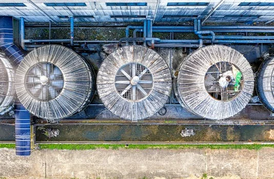
According to US EPA 40 CFR Part 403 (eCFR current text), federal pretreatment rules bar discharges that cause POTW pass-through or interference. Approved programs must set enforceable local limits. Part 403 itself does not publish a single national FOG or TSS number for every food plant; many municipal permits still use TSS < 30 mg/L and FOG < 50 mg/L as local targets. The same part specifically restricts petroleum oil and related mineral oils when they would cause interference or pass-through. In the European Union, Directive 91/271/EEC and BAT reference documents still drive COD limits near < 125 mg/L for many urban and agro-food discharges, which often means multi-stage DAF plus biology.
Hardware follows the permit. Petrochemical sites usually need explosion-proof electrics (ATEX or Class 1 Div 1) and oil-resistant seals. Use of 316L stainless steel is standard where chlorides risk pitting. Municipal plants often want modular trains so they can run near 20% capacity in low season and 100% in peak wet weather without losing flotation stability.
Fine-bubble duty below about 50 μm is also specified when microplastic or algae capture is a project goal. Reported industrial DAF removals in that fine-bubble regime often fall in the 50–80% band for microplastics, which needs tight dissolving tubes and nozzles that limit coalescence. Write material grade, automation level, and local-limit targets into the RFQ so vendors cannot hide behind generic catalogs.
How Much Does a DAF Unit Cost?
Capital cost for industrial DAF units typically ranges from about $20,000 for small 4 m³/h packages to over $300,000 for 300 m³/h systems. Operating cost often falls near $0.12–$0.40 per m³ treated, with energy around 0.15–0.5 kWh/m³ depending on capacity. Compared with sedimentation, DAF costs more per skid but needs far less civil area—about one-fifth the footprint of a circular clarifier at 100 m³/h—so land and concrete can dominate the comparison.
| Capacity (m³/h) | Capital Cost (USD) | Operating Cost (USD/m³) | Energy Use (kWh/m³) | Design Life (Years) |
|---|---|---|---|---|
| 4–20 | $20k – $55k | $0.25 – $0.40 | 0.3 – 0.5 | 15–20 |
| 20–100 | $60k – $150k | $0.18 – $0.30 | 0.2 – 0.4 | 20+ |
| 100–300 | $160k – $350k | $0.12 – $0.22 | 0.15 – 0.3 | 20+ |
ROI usually comes from surcharge and sludge cuts. A dairy at 50 m³/h facing $60,000 per year in FOG surcharges can often cut those charges by about 90% with a $90,000 DAF, giving a payback near 1.7 years. Still budget polymer at $0.05–$0.20/m³ and plan sludge dewatering solutions for DAF-generated float in the O&M model.
Versus Membrane Bioreactors (MBR), DAF has a lower capital entry point and lower energy (about 0.2–0.4 kWh/m³ for DAF versus 0.8–1.2 kWh/m³ for MBR). MBR wins when reuse quality is mandatory; DAF remains the economical primary clarification and pretreatment step. For regional civil and utility rates, adjust global benchmarks with local data such as the wastewater treatment plant cost in Colombia 2025 breakdown.
What Clarifier Selection Criteria Favor DAF?
Clarifier selection criteria favor DAF when solids are light, oily, or float-prone and when site area is tight. Primary gravity clarifiers suit dense mineral solids at low overflow rates. Secondary circular or rectangular settlers polish biological floc. Lamella packs raise settling area in a small box but still rely on particle density above water. DAF is the better match for FOG, algae, and low-density TSS when hydraulic loading up to about 10 m/h is acceptable and pressurized recycle is available.
Footprint for DAF generally runs 0.5–1.5 m² per m³/h of treated flow. Use this five-step checklist before freezing the RFP:
- Define wastewater characteristics: Run 24-hour composite sampling for peak TSS, FOG, and COD. If FOG exceeds 1,000 mg/L, specify A/S above 0.05.
- Set design flow: Size on peak hourly flow, not daily average. An 80 m³/h average often needs a 100 m³/h unit for a 25% buffer.
- Match permit limits: Tie removal efficiency to local discharge rules (for example EU TSS guidance bands near < 60 mg/L for some plant classes).
- Check space and material: Confirm pad area and choose 304 or 316L stainless steel from corrosivity data.
- Compare vendor packages: Score automation, warranty, and local service—not only list price.
| Feature | HydropureWater DAF Line | Tier 1 US Standard | European Modular Model |
|---|---|---|---|
| Flow Range | 4–300 m³/h | 10–250 m³/h | 5–200 m³/h |
| TSS Removal | Up to 98% | Up to 95% | Up to 96% |
| Automation | Full PLC/SCADA Integration | Basic Controls Standard | Remote Monitoring Opt. |
| Material | SS304/SS316L/Duplex | Coated Carbon Steel/SS | SS304/Polypropylene |
When you draft the RFP, lock material of construction, micro-bubble method (multiphase pump versus saturation vessel), and whether you need expandable trains. If future capacity is likely, reference modular sewage treatment system specifications so the vendor prices a path that does not strand the first skid.
Who This Is For and Next Step
This guide is for plant engineers, EPC leads, and procurement managers sizing industrial pretreatment for FOG- or TSS-heavy streams. Look elsewhere if you need full secondary biological treatment, high-salinity water above about 10,000 mg/L TDS without piloting, or reuse-quality effluent that only membranes can meet. If your peak flow, FOG load, and local permit numbers are ready, request a DAF sizing quote with those three figures attached so the duty can be checked against DAF ranges before drawings start.
Frequently Asked Questions
What is the typical removal efficiency of a DAF unit for TSS and FOG?
DAF units typically achieve 90–98% TSS removal and 92–99% FOG removal when chemical pretreatment is adequate. Food plants using DAF-class units often cut influent FOG from about 1,500 mg/L to less than 50 mg/L under common municipal pretreatment permits. Results depend on polymer dose, recycle rate, and whether emulsified oil needs extra coalescing chemistry.
How do I calculate the required recycle rate for my DAF system?
Recycle rate (R) is often estimated from R = (C_sat - C_in) / (C_in - C_eff) * 100%, then checked against the A/S target of 0.02–0.06. For about 400 mg/L influent TSS and 40 mg/L effluent at 40–70 psi saturation, many industrial designs land near a 22% recycle. Always confirm with jar tests and saturator efficiency (f ≈ 0.5–0.8) before freezing pump size.
What are the key differences between DAF and sedimentation?
DAF targets low-density contaminants such as FOG and algae and supports hydraulic loading up to about 10 m/h, roughly 2–5 times higher than many settlers. The trade-off is energy for pressurized air, typically 0.2–0.4 kWh/m³ versus about 0.05–0.1 kWh/m³ for sedimentation. Choose DAF when footprint and floatable solids dominate; choose gravity settling when solids are dense and power must stay minimal.
What industries benefit most from DAF units?
Food processing, petrochemicals, pulp and paper, and municipal algae control benefit most because oils, greases, and light solids dominate those streams. DAF is a weaker fit for wastewater above about 10,000 mg/L TDS or above about 60°C, where bubble stability falls. Pilot or jar-test those edge cases before full-scale purchase.
How much does a DAF unit cost, and what drives price?
Capital costs usually span about $20,000 for 4 m³/h units to $300,000+ for 300 m³/h systems. Drivers include stainless grade (316L versus 304), PLC automation, and add-ons such as chemical dosing skids or thickeners. Operating budgets should also carry polymer ($0.05–$0.20/m³) and float dewatering, not only the skid price.